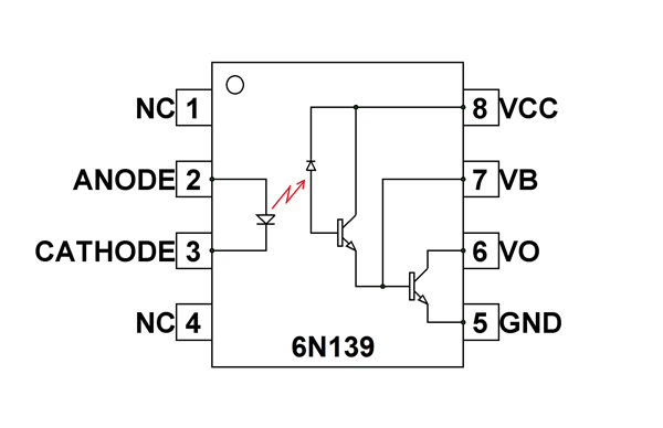
I need to throw 3.3v to 24v DC (Preferably 30v DC) into a 6n137 Opto-isolator to feed a 3.3v input on a nano 3.3v.
Basically, a wide range input. which I may include AC as well.
So, my thinking was to first fire the input through a suitably rated bridge rectifier to obtain DC, and then I was thinking of then going to a suitably rated 5v regulator (there is 5v on the board as well), which then feeds the 6n137 input led through a resistor.
Am I making that too complicated?
The 6n137 led supply i think is around 10mA at 1.4v. I don't think I can stay within the voltage bounds (1,1v - 1.7v) with a simple voltage divider.
Just for context. This is a row of inputs on a device that literally could have anything thrown at it.
The old device has multiple banana plug inputs for 3.3v, 5v, 9v, 12v, 15v etc
All working on voltage dividers.
I want to isolate this input from the processor and reduce the huge footprint of all these banana sockets.
When you say using a voltage comparator... or a constant current source... I have no idea how to design that. I will have to Google.
My simpleton brain just though of a collection of TO92 (or similar) voltage regs of various ranges but the same output. Throw the individual outputs through in4001's and mix them to the Opto-isolator input.
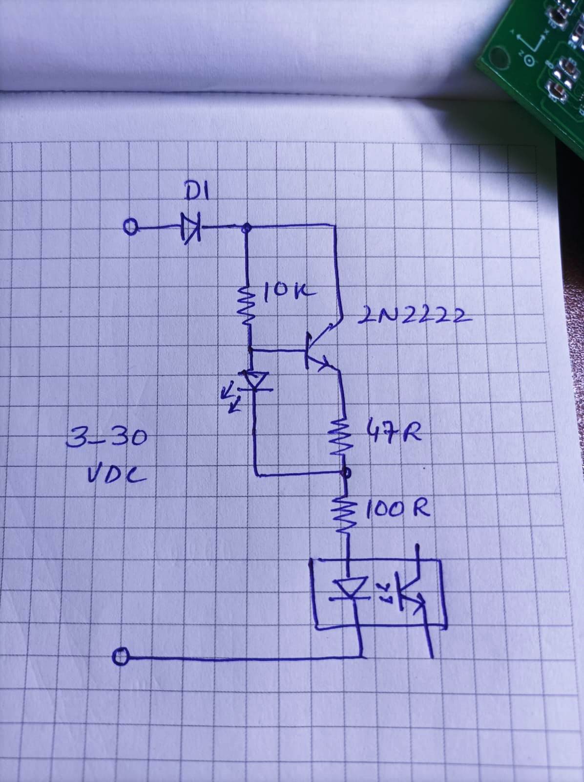
This is constant current circuit which i used many times. just i forgot the correct position of 47R and 100R. so better change positions if circuit does not work. it was confirm working from 5 to 30 volts. not sure for 3.3 volts. give it a try
LED on base is not for light but part of constant current source.
If reverse polarity protection is not needed then remove diode. it will surely start working from 3 volts then.
Thanks all. I have all these components in the workshop, so I will see what works best.
The signal just tells a processor (3.3v high = on) to change the state of indicators on a touchscreen and also trigger outputs.
There are 10 inputs, each with 3.3v, 5v, 9v, 12v, 15v, 18v and 24v input plugs (plus ground).
As you can imagine, that makes 80 input sockets and takes up a HUGE amount of panel space.
I want to reduce that to a single input and ground for each channel so that I can tidy up this old bit of kit.
So overly complicated solutions! It can be done so much simpler: just get a suitable series resistor in the input, and a weak enough pull-up in the output. Unfortunately not for the 6n136, though, you'll have to use a cheaper part.
If you want AC, you can use an AC in DC out type of optocoupler, such as the H11AA1.
For the 6n137: absolute maximum forward current for the LED is 20 mA, but its minimum is 5 mA. If you want <20 mA at 30V, use a 1k5 resistor, but then at 3.3V the current in the LED is just 1.3 mA, not enough for the 6n137 to switch on.
In case of the PC817, the story is very different.
Vf of the LED is 1.2V, CTR is at least 50% (for some versions up to 300% guaranteed).
Use a largish pull-up resistor, to limit the collector current. 10k gives 0.33 mA Ic at Vcc = 3.3V.
On the input side, a 2k2 series resistor. Now you have 13 mA at 30V, down to 0.95 mA at 3.3V.
This will work great with all signals under about 10 kHz. Higher frequencies may be a bit iffy.
For the H11AA1 the calculations are different as it's minimum CTR is just 20% but it its LEDs are rated up to a very high 60 mA. A weaker pull-up resistor of 22k would be the easiest solution - 0.15 mA Ic, which at 20% CTR needs >0.75 mA through the LED.