But im skeptical about if it will work or fry the arduino.
Last time I made this circuit the central chip in the arduino was so hot that it burned my skin a little.
Although the arduino doesnt seem damaged or behave like its damaged. I am not sure if it was the circuit or something else that caused the overheat.
Take a look at circuit 8A here. It's driving a relay coil but it will also work with a motor.
V+ is the positive terminal of the battery. The negative battery terminal goes to ground.
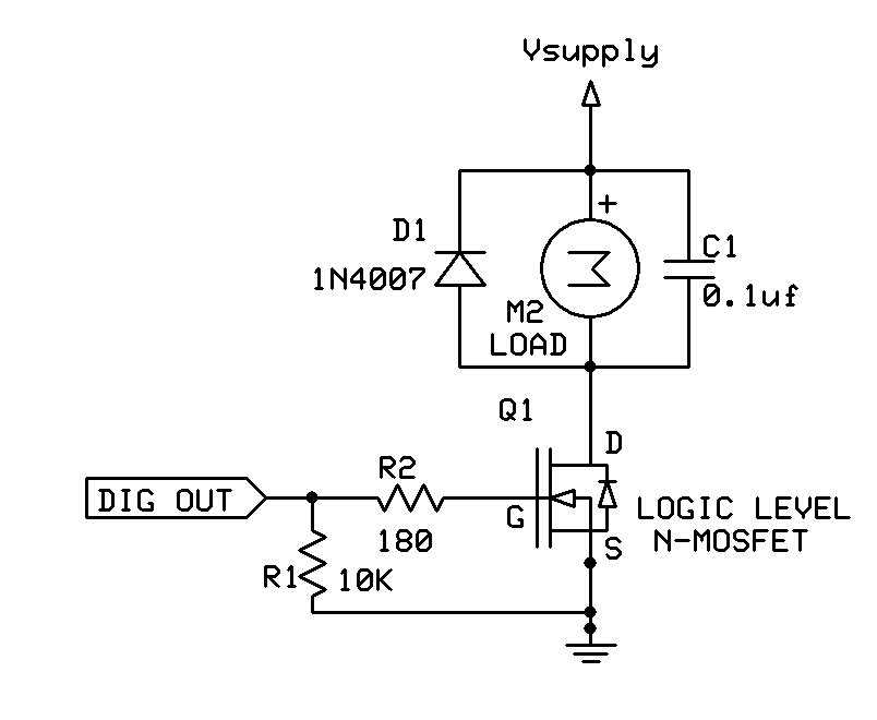
Of course, the transistor needs to be rated for the motor current (Amps or milliamps). Voltage is not a problem... Just about any transistor can handle 9V.
The diode protects the transistor and Arduino from the high voltage inductive kickback when the motor is turned-off.
The resistor prevents excess current from the Arduino into the transistor base (which could potentially damage either one, but is more likely to damage the Arduino).
You have no current limiting resistor from D13 to the base of the NPN. You were likely drawing way too much current from that pin, causing the Atmega processor to overheat. Sometimes they survive, sometimes they don't.
I'd replace the NPN with a logic level MOSFET; that's the easiest way to get this going. And don't forget the voltage divider on the A3 pin so you don't exceed the voltage rating of that pin.
Unless I have misunderstood your battery is the wrong way round. The long bar is positive, the short one negative. When I first learnt about electrical circuits I remembered this by imagining that I could cut the long bar in half and use the 2 pieces to make a + sign.