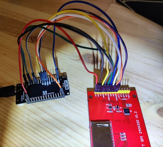
ILI9341 display: white screen issue with ESP32

Hey everyone.

I recently got my TFT 2.8" ILI9341 display and I'm trying to get a demo working on it on my ESP32 (Lolin D32) but I just can't get it to work. No matter the code, library, code example, or wiring I try I it just stays on the white screen. I don't get any errors on the IDE either.

I power the board via USB from my PC btw.

Libraries I have:

  • Adafruit GFX Library
  • Adafruit ILI9341
  • Adafruit TouchScreen
  • TFT_eSPI

User_setup.h on tft_espi library code (I'll just show the uncommented lines)

#define ILI9341_DRIVER

//#define TFT_MISO 19
#define TFT_MOSI 23
#define TFT_SCLK 18
#define TFT_CS   15  // Chip select control pin
#define TFT_DC   2  // Data Command control pin
#define TFT_RST  4  // Reset pin (could connect to RST pin)
//#define TFT_RST  -1  // Set TFT_RST to -1 if display RESET is connected to ESP32 board RST

#define TOUCH_CS 21     // Chip select pin (T_CS) of touch screen

#define LOAD_GLCD   // Font 1. Original Adafruit 8 pixel font needs ~1820 bytes in FLASH
#define LOAD_FONT2  // Font 2. Small 16 pixel high font, needs ~3534 bytes in FLASH, 96 characters
#define LOAD_FONT4  // Font 4. Medium 26 pixel high font, needs ~5848 bytes in FLASH, 96 characters
#define LOAD_FONT6  // Font 6. Large 48 pixel font, needs ~2666 bytes in FLASH, only characters 1234567890:-.apm
#define LOAD_FONT7  // Font 7. 7 segment 48 pixel font, needs ~2438 bytes in FLASH, only characters 1234567890:-.
#define LOAD_FONT8  // Font 8. Large 75 pixel font needs ~3256 bytes in FLASH, only characters 1234567890:-.
//#define LOAD_FONT8N // Font 8. Alternative to Font 8 above, slightly narrower, so 3 digits fit a 160 pixel TFT
#define LOAD_GFXFF  // FreeFonts. Include access to the 48 Adafruit_GFX free fonts FF1 to FF48 and custom fonts

#define SMOOTH_FONT
#define SPI_FREQUENCY  27000000

// Optional reduced SPI frequency for reading TFT
#define SPI_READ_FREQUENCY  20000000

// The XPT2046 requires a lower SPI clock rate of 2.5MHz so we define that here:
#define SPI_TOUCH_FREQUENCY  2500000

full code: Untitled - Pastebin (sorry can't paste the full code here, over 9k chars)

Connections:

  • VCC - 3V (and tried 5V)
  • GND - GND
  • CS - 15
  • DC - 2
  • RST - 4
  • MOSI - 23
  • SCK - 18

also connected later:

  • Touch_CS - 21
  • Touch_DO - 19
  • Touch_DIN - MOSI
  • Touch_CLK - SCK

Used Tech Note 044 - ESP32 how to use ILI9341 TFT displays - YouTube and ILI9341 TFT LCD to ESP32 - Full HOW TO for display, SD card and Touch. Using TFT_eSPI driver - YouTube most recently as my guide

Bought this one 2.8 inch ili9341 240x320 spi tft lcd display touch panel spi serial port module Sale - Banggood.com

Is the screen broken or am I just doing something wrong? I know I'm a beginner in all of this but pretty sure it should've worked at some point but nothing. Getting very worried about this.

Good video BUT:

I would prefer if he showed how to use one of the ready-made User_Setups and how to select that Setup.
I would prefer if he showed how to install library via Library Manager and not mention any ZIP file upload.

He shows how to wire the breadboard. Neatly trimmed wires with consistent colours.
Excellent tip to show pinouts from top view. Slight parallax error from camera when showing header pins and associated breadboard rows.

Bodmer's TFT_eSPI library is excellent. Lots of examples. Ready-made Setups e.g. to suit ESP32 and ILI9341.

Copy the exact wiring specified in the Setup.
Run all the examples.

Be happy.

When you have been 100% successful. Only then try custom wiring, writing custom User_Setup, investigate any new developments on the Beta, ...

David.

david_prentice:
Bodmer's TFT_eSPI library is excellent. Lots of examples. Ready-made Setups e.g. to suit ESP32 and ILI9341.

Copy the exact wiring specified in the Setup.
Run all the examples.

I looked up the user_setups and I believe the Setup1_ILI9341.h was most appropriate for me but it says to connect CS to pin D8, which my board doesn't have. I tried different pins like 5 and 18 but none of the examples for 320x240 worked. The other setups seemed to be parallel or stm (?) setups, should I try those as well?

Also, very confused how it doesn't mention connecting MOSI or SCK. So being the clueless chap that I am, I tried without and also connecting MOSI to 23 and SCK to 14.

Ok, take the nearest User_Setup and change CS from 8 to 5.

Obviously change the wiring to 5.

Personally, I use these:

//#define TFT_SCK  18 //.kbv HW_SPI
//#define TFT_MISO 19 //.kbv HW_SPI
//#define TFT_MOSI 23 //.kbv HW_SPI
#define TFT_CS   5  // Chip select control pin was D8
#define TFT_DC   13  // Data Command control pin
#define TFT_RST  12  // Reset pin (could connect to NodeMCU RST, see next line)
//#define TFT_RST  -1    // Set TFT_RST to -1 if the display RESET is connected to NodeMCU RST or 3.3V
#define TOUCH_CS 25  // Chip select pin (T_CS) of touch screen

But quite honestly, it is best to start with a ready-made example Setup and follow it meticulously.

There is time for custom Setup when you have verified that the example Setup works with all the example sketches.

David.

Edit. Added my HW_SPI wiring for SCK, MISO, MOSI

david_prentice:
Ok, take the nearest User_Setup and change CS from 8 to 5.

Obviously change the wiring to 5.

Yeah I understand.

I still seem to be struggling with getting it to work.

From user_setup_select.h I uncommented the Setup1_ILI9341.h and commented #include <User_Setup.h>:

// Only ONE line below should be uncommented.  Add extra lines and files as needed.

//#include <User_Setup.h>           // Default setup is root library folder

#include <User_Setups/Setup1_ILI9341.h>  // Setup file configured for my ILI9341

And this is the Setup1_ILI9341.h:

#define ILI9341_DRIVER

#define TFT_CS   5  // Chip select control pin D8
#define TFT_DC   13  // Data Command control pin
#define TFT_RST  12  // Reset pin (could connect to NodeMCU RST, see next line)
//#define TFT_RST  -1    // Set TFT_RST to -1 if the display RESET is connected to NodeMCU RST or 3.3V

Connections now:

  • VCC - 3V
  • GND - GND
  • LED - 3V
  • CS - 5
  • DC - 13
  • RST - 12
  • SCK - 4 (Tried without having this connected as well)
  • MOSI - 23 (Tried without having this connected as well

Tried disconnecting the SCK and MOSI as well, tried different examples but still not working. Just a bright white screen.

Any idea what could be the fault here? Do you think the display is broken?

I still recommend that you use Bodmer's ready-made User_Setup

I have edited #3 to show my HW_SPI wiring.

David.

david_prentice:
I still recommend that you use Bodmer's ready-made User_Setup

I have edited #3 to show my HW_SPI wiring.

David.

Do you mean the Setup1_ILI9341.h User_Setup or the default User_setup.h one? I've tried both now.

The Setup1_ILI9341.h with default wirings (with and without SCK/MOSI/MISO) with the only change is changing the pin from 8 to 5 (since my board doesn't have #8 pin). I also tried your wiring code (both the code and wiring) but it didn't work either.

And I also tried the default one (User_setup.h) where I changed the stuff as mentioned on the #1 post.

I'm not sure what else to try.
Also, I'd like to say I appreciate you assisting me with this and being so quick with your replies as well.

Setup1 looks like ESP8266 rather than ESP32.

Please understand that what I say is not what I actually do.
Some ESP32 boards have D# numbers and some don't.

With ESP32 the safest thing is to use the GPIO# numbers. e.g. GPIO5 = 5, GPIO13 = 13, ...
With ESP8266 you should always use the D# names.

Obviously the correct pin numbers depend on you selecting the correct ESP board in the IDE.

David.

david_prentice:
With ESP32 the safest thing is to use the GPIO# numbers. e.g. GPIO5 = 5, GPIO13 = 13, ...
With ESP8266 you should always use the D# names.

Obviously the correct pin numbers depend on you selecting the correct ESP board in the IDE.

Makes sense. Though I couldn't find anything else for the ILI9341 screen that weren't SMT or parallel boards, whatever those mean.
Assuming I've understood this correctly, shouldn't it just be possible to change the pin numbers on User_Setup.h -file to what we've listed on this thread? Are there other causes that could make the screen white and unresponsive to IDE commands?
I do have the Lolin D32 board selected on the IDE, yeah. Upload speed at 921600 and flash frequency at 80MHz, in case those make a difference.

I read couple more articles/forum threads and some of them mentioned about putting RST onto 3V and/or adding resistors like 10k. Since I don't use these, could that be the reason it doesn't display anything? I can't imagine it is but just trying to find anything that'd explain it so I wouldn't need to buy and wait for a new display.

On my PC this is the file for Lolin-32
C:\Users\David Prentice\AppData\Local\Arduino15\packages\esp32\hardware\esp32\1.0.4\variants\lolin32\pins_arduino.h

...
static const uint8_t SS    = 5;
static const uint8_t MOSI  = 23;
static const uint8_t MISO  = 19;
static const uint8_t SCK   = 18;
...

In other words, a pin marked SCK goes to GPIO18

Looking at photos of the Lolin D32 pcb it seems that the pins are marked by their GPIO#
So the pin marked 18 is GPIO18 and used for SCK

If you want to use names like A0 in your Arduino functions it refers to GPIO36

putting RST onto 3V and/or adding resistors like 10k. Since I don't use these, could that be the reason it doesn't display anything?

You should always connect the RST pin on a Red SPI board.
You should always use it in the constructor.

Remember that Adafruit and others might have hardware pullups on RST.
It is in their interest to crash Red board owners. And the trick works pretty well.

Think about it. Thousands of Red SPI owners use TFT_eSPI library with ESP32.
Many more use it with ESP8266 and STM32

David.

david_prentice:

...

static const uint8_t SS    = 5;
static const uint8_t MOSI  = 23;
static const uint8_t MISO  = 19;
static const uint8_t SCK   = 18;
...


In other words, a pin marked SCK goes to GPIO18

Looking at photos of the Lolin D32 pcb it seems that the pins are marked by their GPIO#
So the pin marked 18 is GPIO18 and used for SCK

I also looked at this http://hobbycomponents.com/images/forum/Wemos_Lolin_D32_Diagram_HCWEMO0014.png to see that I'm connecting the board pins onto the right display pins.

Just to verify, do my wirings and user_setup seem right to you:

User_Setup.h (the ready-user_setup didn't work so I'll try this one again):

#define ILI9341_DRIVER
#define TFT_MISO 19
#define TFT_MOSI 23
#define TFT_SCLK 18
#define SMOOTH_FONT
#define SPI_FREQUENCY  27000000
#define SPI_READ_FREQUENCY  20000000
#define SPI_TOUCH_FREQUENCY  2500000

and I uncommented User_setup.h from User_setup_select.h (and checked that other setup includes were commented out):

// Only ONE line below should be uncommented.  Add extra lines and files as needed.

#include <User_Setup.h>           // Default setup is root library folder

Wire connections (Display's pin - D32 pin):
MISO - GPIO19
MOSI - GPIO23
SCK - GPIO18
CS - GPIO5
DC - GPIO2
RESET - GPIO4
TOUCH_CS - GPIO21
GND - GND
LED - 3V
VCC - 5V

And using TFT_ESPi library's 320x240 examples? Does everything seem proper? I'm only getting that pesky blank white screen and nothing more.

david_prentice:
You should always connect the RST pin on a Red SPI board.
You should always use it in the constructor.

Remember that Adafruit and others might have hardware pullups on RST.
It is in their interest to crash Red board owners. And the trick works pretty well.

Fair point.
But so, if I use it in the constructor, doesn't that mean I can apply it to "any" GPIO pin then as long as I edit the constructor? E.g. *#define TFT_RST 4 * where "4" is the GPIO # pin?

david_prentice:
If you want to use names like A0 in your Arduino functions it refers to GPIO36

Well, that would certainly explain why I couldn't get my analog light sensor to work. I tried to use A0 on the IDE code but used a completely wrong GPIO pin.

Everything should be very straightforward.

Your User_Setup should specify DRIVER, CS, DC, RST, TOUCH_CS, FREQUENCY, TRANSACTIONS
as you can see in a ready-made User_Setup.

Your actual wiring must match these defines. SCK, MOSI, MISO are fixed in hardware. You must use the HW pins. But the User pins like CS, DC, RST, ... can be on any digital GPIO pins. (note that some ESP32 pins are Analog-only)

I am probably in a different country.

If you want readers to check, you need to paste your defines. And post a photo of your actual wiring.

You have to be meticulous when wiring. I suggest writing a paper check list.
However, Bodmer's User_Setup means that you configure it once. And all the examples will work.
i.e. you don't need to edit any constructor() statements.

David.

Oh awesome. That's very good to know.

Also for checking:

Defines:

#define ILI9341_DRIVER[color=#222222][/color]
#define TFT_MISO 19
#define TFT_MOSI 23
#define TFT_SCLK 18
#define TFT_CS   5  // Chip select control pin
#define TFT_DC    2  // Data Command control pin
#define TFT_RST   4  // Reset pin (could connect to RST pin)
//#define TFT_RST  -1  // Set TFT_RST to -1 if display RESET is connected to ESP32 board RST

#define TOUCH_CS 21     // Chip select pin (T_CS) of touch screen
#define SMOOTH_FONT[color=#222222][/color]
#define SPI_FREQUENCY  27000000[color=#222222][/color]
#define SPI_READ_FREQUENCY  20000000[color=#222222][/color]
#define SPI_TOUCH_FREQUENCY  2500000

Wirings on attachments.

I realize my wiring is very poor in terms of visibility (and aesthetics) but I can't get a bigger breadboard atm nor can I solder any connections yet. Which is why I made a wiring diagram that uses the same pins connections along with the same wire colors.

The further two wirings on the side-photo are the 5V and 3V wires for VCC and LED pins respectively.

If you want readers to check, you need to paste your defines. And post a photo of your actual wiring.

I do not see your User_Setup.h defines pasted anywhere.
You have posted a good Fritzing.

You have posted a photo that is upside down relative to the Fritzing.
The coloured wires are different to the Fritzing colours.

And it is not possible to identify which wire goes to which terminal on your Lolin.

Do we have a language problem?
Or are you just trolling?

It is a good idea to write a paper checklist.
It is a good idea to use consistent wire colours
It is a good idea to post photos with the correct rotation and clearly show Lolin terminals.

You are using your breadboard wisely. i.e. header pins in breadboard rows. single jumper wires to Lolin-D32
There is a current thread which involves 3x as many wires linking level shifters.

This thread only goes to show that simple wiring must be done meticulously.
And wiring that is 3x more complex will be 3x harder.

David.

david_prentice:
Do we have a language problem?
Or are you just trolling?

I'm sorry. I can assure you there's no language issue nor am I by any means trolling. I'm just very new to this and seemingly there're a bunch of misunderstandings on my part.

david_prentice:
I do not see your User_Setup.h defines pasted anywhere.

The code block, that I posted in my previous post, is the User_setup.h that has all the defines that aren't commented out. Is there other stuff I should've included there that I didn't notice?

david_prentice:
You have posted a photo that is upside down relative to the Fritzing.
The coloured wires are different to the Fritzing colours.

And it is not possible to identify which wire goes to which terminal on your Lolin.

I recolored the wires in the Fritzing diagram to better match the cable colors on the IRL photos. I also added an additional photo there from a side-view + some additional texts so if it could help in making sense of my wirings. I couldn't find a better way to make it more clear without cutting the cables into short, neat pieces.

I can see how the images don't do justice and with photoshopping and moving the pieces and wires around on the board, I can't do better. So I get it if checking the connections isn't plausible.

From post #0

#define ILI9341_DRIVER

//#define TFT_MISO 19
#define TFT_MOSI 23
#define TFT_SCLK 18
#define TFT_CS   15  // Chip select control pin
#define TFT_DC   2  // Data Command control pin
#define TFT_RST  4  // Reset pin (could connect to RST pin)
//#define TFT_RST  -1  // Set TFT_RST to -1 if display RESET is connected to ESP32 board RST

#define TOUCH_CS 21     // Chip select pin (T_CS) of touch screen

From the Fritzing:

#define ILI9341_DRIVER

#define TFT_MISO 19  //.kbv <<<<<<<
#define TFT_MOSI 23
#define TFT_SCLK 18
#define TFT_CS   5  // Chip select control pin .kbv <<<<<
#define TFT_DC   2  // Data Command control pin
#define TFT_RST  4  // Reset pin (could connect to RST pin)
//#define TFT_RST  -1  // Set TFT_RST to -1 if display RESET is connected to ESP32 board RST

#define TOUCH_CS 21     // Chip select pin (T_CS) of touch screen

I still can't identify Lolin pins from your photos. But the Fritzing does not agree with #0

In a protracted thread it is wise to re-post up-to-date information. Especially when specifically asked.

It is not difficult to write your connections down on paper. Handy to write the wire colour too.
Then you can tick off each connection in your checklist.
You have good eyesight and can identify each wire end.
A foreign reader can possibly help if you have clear photos.
If the wire colours are in your checklist, a foreign reader can distinguish "difficult" photos.

Seriously. Five minutes effort on your part makes all the difference. And it probably means you spot most of your own errors. (Which is what we all had to do before the Internet)

David.

david_prentice:
I still can't identify Lolin pins from your photos. But the Fritzing does not agree with #0

In a protracted thread it is wise to re-post up-to-date information. Especially when specifically asked.

It is not difficult to write your connections down on paper. Handy to write the wire colour too.
Then you can tick off each connection in your checklist.
You have good eyesight and can identify each wire end.
A foreign reader can possibly help if you have clear photos.
If the wire colours are in your checklist, a foreign reader can distinguish "difficult" photos.

Seriously. Five minutes effort on your part makes all the difference. And it probably means you spot most of your own errors. (Which is what we all had to do before the Internet)

David.

I just realized I didn't paste all the user_setup.h code. That was my bad. I updated it on #13.

I do have a paper where I check the wirings very carefully. I'm 100% sure they are on the exact pins as the user_setup.h has them. I can add the paper to the photo if it'll help others read the wirings but I imagined it wouldn't really make it easier to see where the pins are actually connected, which I sadly can't really make any better atm. Or at least I can't think of any ways without getting a bigger board, soldering, or shortening the wires.

I managed to find a clearer way to show the wirings. No breadboard but now the connections are clear, it's properly rotated relative to the diagram, and all wires have their unique colors. I also updated the Fritzing diagram accordingly.

I crossed everything on my paper and still can't get any of the examples to work. Any idea what could be the cause?

User_setup.h uncommented lines:

#define ILI9341_DRIVER

#define TFT_MISO 19
#define TFT_MOSI 23
#define TFT_SCLK 18
#define TFT_CS   5  // Chip select control pin
#define TFT_DC    2  // Data Command control pin
#define TFT_RST   4  // Reset pin (could connect to RST pin)

#define LOAD_GLCD   // Font 1. Original Adafruit 8 pixel font needs ~1820 bytes in FLASH
#define LOAD_FONT2  // Font 2. Small 16 pixel high font, needs ~3534 bytes in FLASH, 96 characters
#define LOAD_FONT4  // Font 4. Medium 26 pixel high font, needs ~5848 bytes in FLASH, 96 characters
#define LOAD_FONT6  // Font 6. Large 48 pixel font, needs ~2666 bytes in FLASH, only characters 1234567890:-.apm
#define LOAD_FONT7  // Font 7. 7 segment 48 pixel font, needs ~2438 bytes in FLASH, only characters 1234567890:-.
#define LOAD_FONT8  // Font 8. Large 75 pixel font needs ~3256 bytes in FLASH, only characters 1234567890:-.
#define LOAD_GFXFF  // FreeFonts. Include access to the 48 Adafruit_GFX free fonts FF1 to FF48 and custom fonts
#define SMOOTH_FONT

#define SPI_FREQUENCY  40000000
#define SPI_READ_FREQUENCY  20000000
#define SPI_TOUCH_FREQUENCY  2500000

Your wiring looks fine. Much easier to check now !

I would set SPI_FREQUENCY to 27MHz
and add this to your User_Setup

#define SUPPORT_TRANSACTIONS

Perhaps your screen is damaged. Perhaps a Dupont wire is damaged.

David.