I recently bought a SIM 808 EVB-V3.2 module and I wanted to do a basic test.
I made use of an example code from the DFRobot_sim808.h library
From the following code I want to recieve a call from the sim 808 module
#include <DFRobot_sim808.h>
#include <SoftwareSerial.h>

#define PIN_TX    10
#define PIN_RX    11
SoftwareSerial mySerial(PIN_TX,PIN_RX);
DFRobot_SIM808 sim808(&mySerial);//Connect RX,TX,PWR,

//Mobile phone number,need to change
#define PHONE_NUMBER  "8116***186"

//DFRobot_SIM808 sim808(&Serial);

void setup() {
  mySerial.begin(9600);
  Serial.begin(9600);
  //********Initialize sim808 module*************
  while(!sim808.init()) {
      delay(1000);
      Serial.print("Sim808 init error\r\n");
  }
  Serial.println("Sim808 init success");
  Serial.println("Start to call ...");

  //*********Call specified number***************
  sim808.callUp(PHONE_NUMBER);
}
void loop() {
  //nothing to do
}
but when I run my program I am getting the "sim 808 init error"
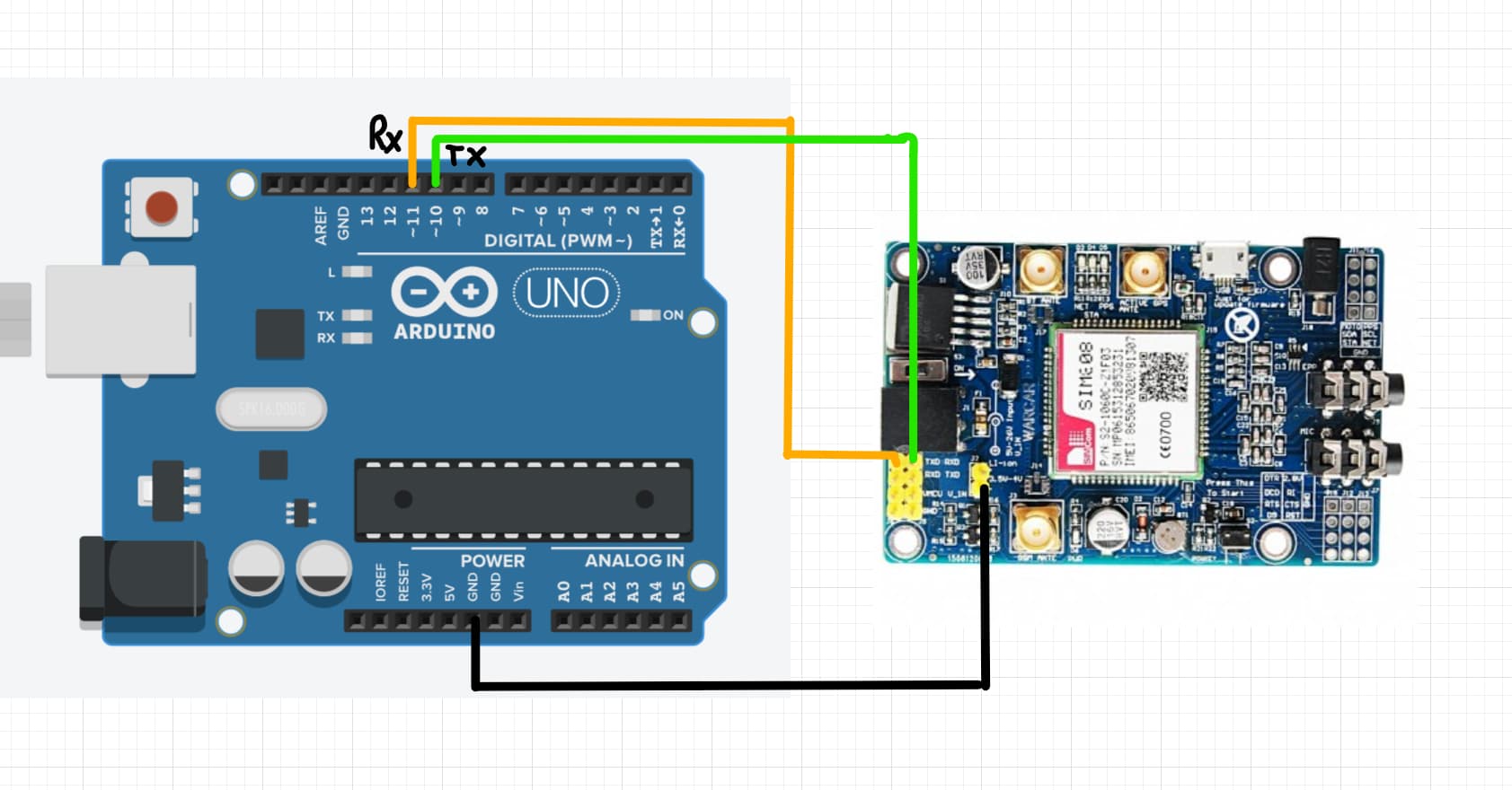
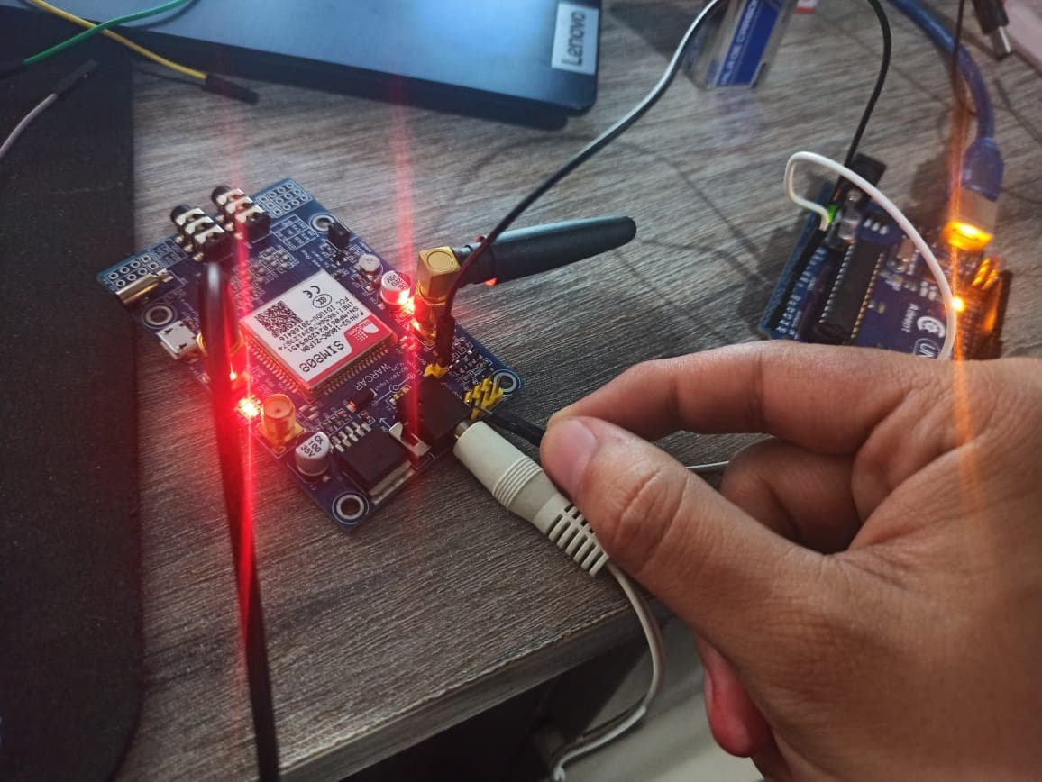
I am powering the module with 9V 2A, and my connections are like this:
Physical connections:
I don't know why I am getting that error, the module seems it's recognizing the Sim card because the second led is blinking every 3 seconds.
Any suggestion would be very helpful
horace
November 10, 2022, 8:00am
2
have a look at car-tracking-system-with-the-sim808-module - it appears to show different Arduino <> SIM connections to your circuit
The connections are the same
pin 10(TX) -> RX
horace
November 10, 2022, 9:07am
5
I was looking at the diagram of the Mega which has pin connections 10 and 11 the other way around??
I tried that and I'm getting the same
horace
November 10, 2022, 9:31am
7
maybe worth seeing if you can get basic AT commands to work with software-serial
check the voltages on Tx and Rx should be 5volts when idle
It was exactly the first thing I tried, I even made a post about that: Serial Terminal not working with AT commands - #11 by deluxen123
unfortunately I don't have a multimeter, but I tried to check the voltage with this little program:
float lectura;
float volt;

void setup() {
  // put your setup code here, to run once:
  Serial.begin(9600);
  pinMode(A0,INPUT);
}

void loop() {
  // put your main code here, to run repeatedly:
  lectura = analogRead(A0);
  volt = lectura /1023 * 5.0;
  Serial.println(volt);

  delay(2000);
}
I got from both TX and RX 5 volts
I know that this is not the best way to measure the Voltage but this is all I've got
horace
November 10, 2022, 1:25pm
9
The first thing I test with a modem is response to AT commands
I tried with this program:
#include <SoftwareSerial.h>

SoftwareSerial softSerial(7, 8);  // Rx, Tx


uint32_t baud[] = {
                       300,
                       600,
                      1200,
                      2400,
                      4800,
                      9600,
                     19200,
                     38400,
                     57600,
                     74880,
                    115200
                  };

void setup()
{

  Serial.begin(9600);

  for (uint8_t i = 0; i < sizeof(baud) / sizeof(baud[0]); i++)
  {
    softSerial.begin (baud[i]);

    Serial.print("Trying @ ");
    Serial.println(baud[i]);

    softSerial.println("AT");

    unsigned long start = millis();

    while (millis() - start < 500)
    {
      while (softSerial.available() > 0)
      {
        Serial.write(softSerial.read());
      }
    }

  }
}


void loop()
{}
and I got this
I was able to get basic AT commands to work with software serial!
I just added AT+IPR=9600 right before the loop
and now I'm getting a readible answer from the module
I even tried with a little program to introduce AT commands
#include <SoftwareSerial.h>
SoftwareSerial SIM808(7, 8); //Seleccionamos los pines 7 como Rx y 8 como Tx

void setup()
{
 SIM808.begin(9600);
 Serial.begin(9600);

 SIM808.println("AT+IPR=9600");

 delay(100);
}

void loop()
{
 //Envíamos y recibimos datos
 if (Serial.available() > 0)
 SIM808.write(Serial.read());
 if (SIM808.available() > 0)
 Serial.write(SIM808.read());
}
and it's working, I even was able to make a call to myself!