Hi,
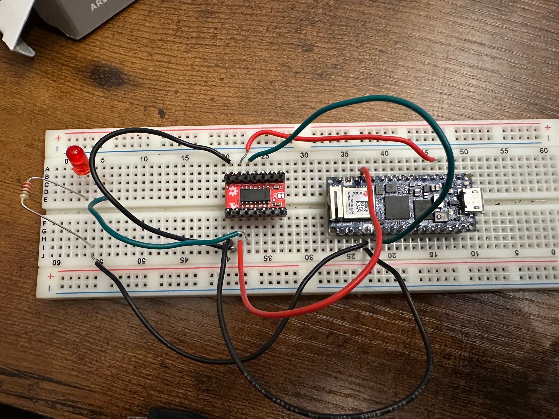
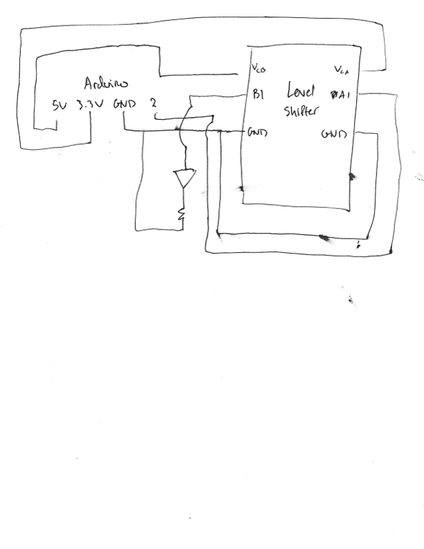
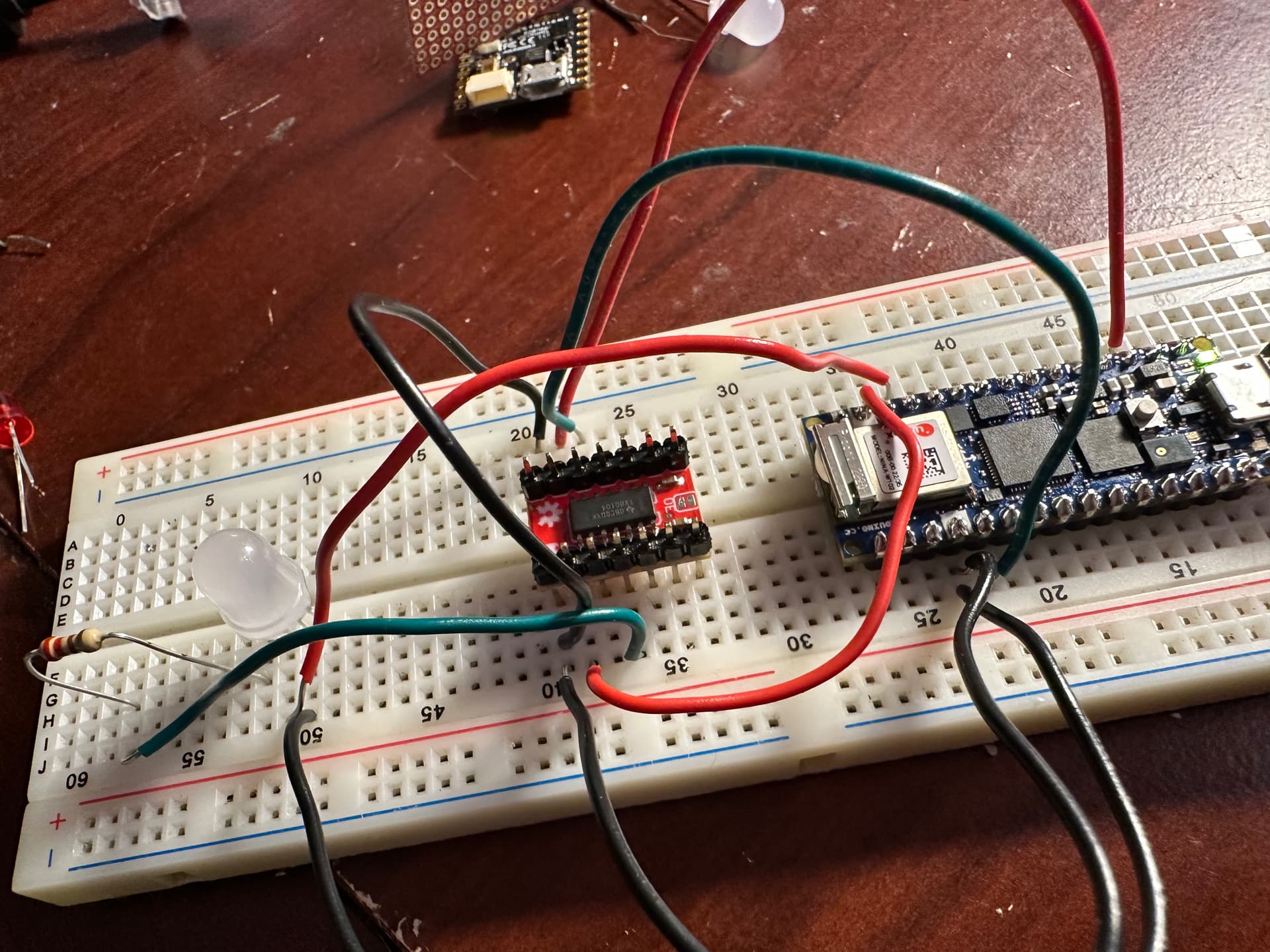
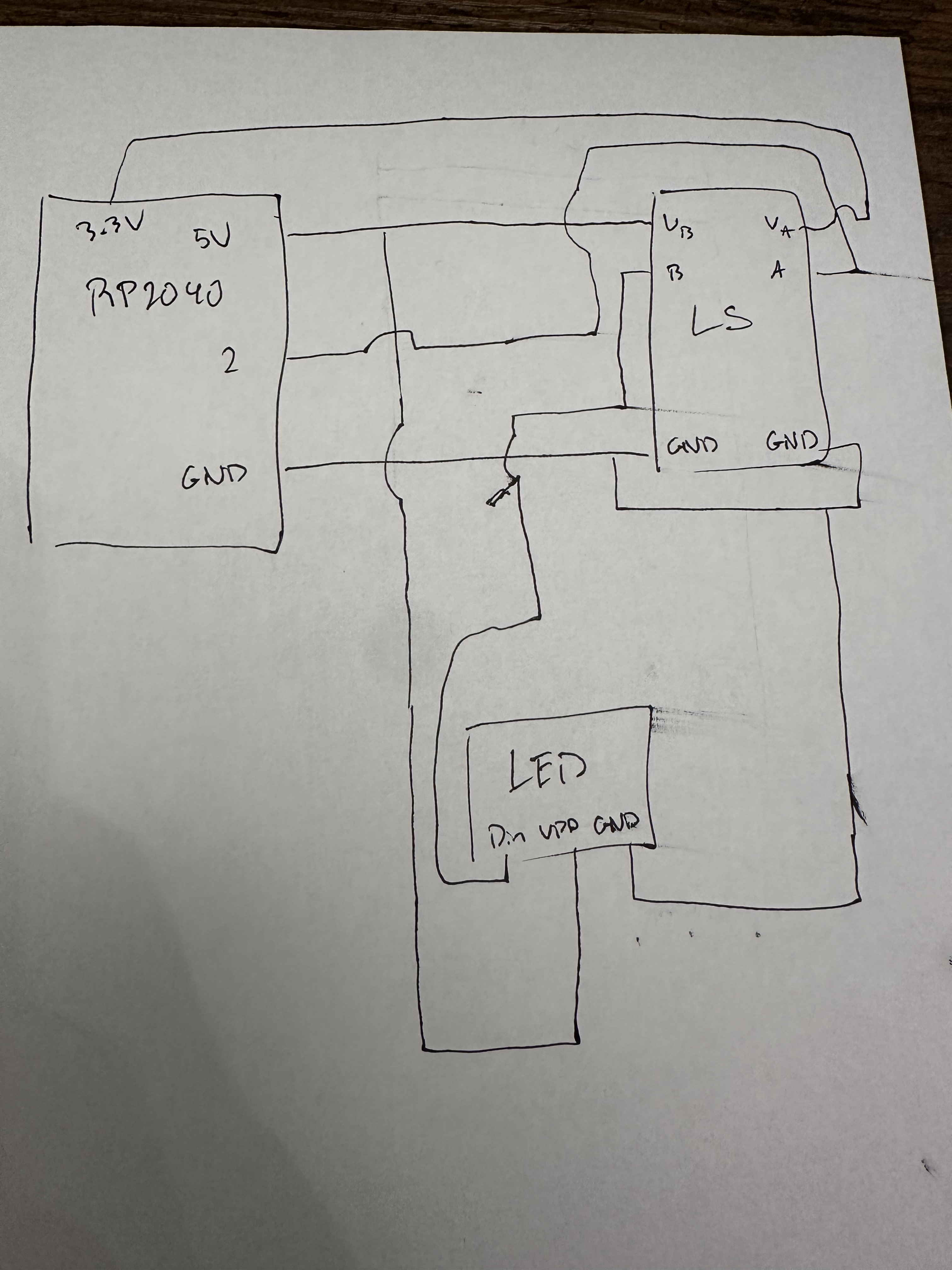
I'm having trouble getting the Sparkfun TXB0104 to work. I have the following connections, which if implemented properly the LED should be on when pin 2 is HIGH, however it is not. Any guidance would be greatly appreciated.
Hi,
I'm having trouble getting the Sparkfun TXB0104 to work. I have the following connections, which if implemented properly the LED should be on when pin 2 is HIGH, however it is not. Any guidance would be greatly appreciated.
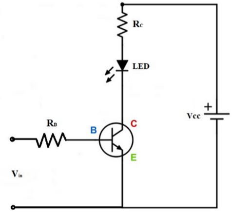
The level shifter is not designed for high (or even LED) current loads, and you don't need one for an LED. Just choose a resistor that limits the LED current to a safe value for the port pin of whatever MCU is on the board you are using.
What IS that board?
I don't know what's the purpose of the level shifter here. Some testing?
Anyway you give 3.3V on the right side together with 5V signal from arduino?
What board is it?
I'm just testing the level shifter with a standard LED before implementing a diffused LED that has a 5V operating voltage. The board used is an RP2040 which logic is only 3.3V.
For your WS2812 signal level shifter is ok. Not for the LED you have on your photo.
Thank you for the guidance. I tried using the WS2812 prior to a regular LED and couldn't get it to work. I'd also like to use an H-Bridge or Servo motor with the RP2040 or any board with 3.3V. Would a level shifter work for those as well?
Depends on the H-bridge. You don't necessarily even need it.
Anyway, logic level shifter is for logic level signals, not for powering anything (not even that red LED).
It's not a boost converter.
Okay - what about pin 9 in the servo diagram and the EN, 1A and 2A pins with the H-Bridge? Both need 5V. If the RP2040 logic pins are 3.3V would the level shifter be feasible/needed?
Most servos are fine with 3.3V position control signals. They MUST be powered separately, with a power supply capable of providing the required current (at least 1 Ampere per servo for small servos, 2.5 Amperes per servo for large ones like the MG996R).
You can certainly find antique parts such as the SN754410 (over 30 years old!) that may not work well with 3.3V logic levels, but why bother when so many other modern, more efficient H-bridges are available? Pololu has the best selection, and very complete user guides.
Most servos accept 3-5V signals.
SN754410 datasheet gives 2-5.5V logic levels, so it's ok with 3.3V as well
Okay, thank you!
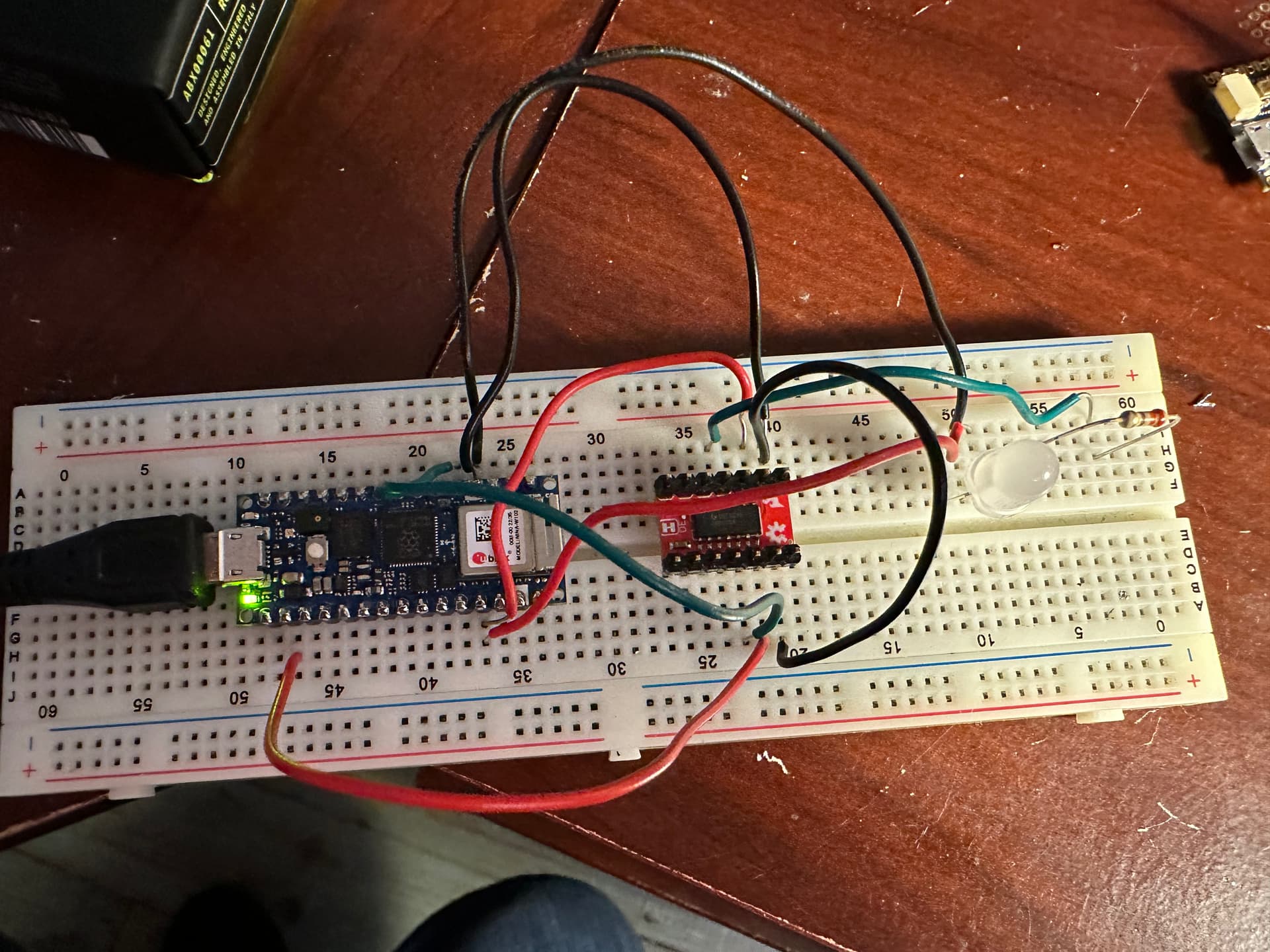
As for the WS2812, I'm still having trouble implementing. Attached are some photos and the code.
#include <FastLED.h>

// How many leds in your strip?
#define NUM_LEDS 1

// For led chips like WS2812, which have a data line, ground, and power, you just
// need to define DATA_PIN.  For led chipsets that are SPI based (four wires - data, clock,
// ground, and power), like the LPD8806 define both DATA_PIN and CLOCK_PIN
// Clock pin only needed for SPI based chipsets when not using hardware SPI
#define DATA_PIN 2
#define CLOCK_PIN 13

// Define the array of leds
CRGB leds[NUM_LEDS];

void setup() {
   FastLED.addLeds<WS2812, DATA_PIN, RGB>(leds, NUM_LEDS);
}

void loop() {
  // Turn the LED on, then pause
  leds[0] = CRGB::Red;
  FastLED.show();
  delay(500);
  // Now turn the LED off, then pause
  leds[0] = CRGB::Black;
  FastLED.show();
  delay(500);
}
You have not provided enough information about your setup or the problem. The photos are of marginal usefulness.
Please read and follow the instructions in the "How to get the best out of this forum" post, linked at the head of every forum category.
Logic level shifters are generally slow, and I don't know of an example of using a logic level shifter with the WS2812. If you are following a tutorial, post a link to it.
The very best approach is to use 5V MCUs with 5V sensors and devices, and 3.3V MCUs with 3.3V sensors and devices, which are now in the vast majority.
Keep in mind that 5V logic will soon be obsolete and a thing of the past.
Not all of them. And I have several examples.
The very simple logic level shifters made with FETs and pull-up resistors are indeed slow. They work ok when shifting i2c bus signals. They will work with ws2812, but only with luck. I tried it once and it did kinda work but it was right on the edge. If I moved my hand near the circuit, the LEDs would go crazy. Checking the input and output signals with a 'scope, I could see that the shifter was turning a nice clean square-edged signal into a sawtooth mess. So I would not recommend that type of shifter for WS2812 or any similar type of LED.
But the shifter shown in the photos is not a simple FET/resistor type, I think. I can't read the markings on the chip, but it might be a chip dedicated for level shifting and should be able to source a decent amount of current and work at high speeds.
I know that 74HCT-series logic chips are ideal for level shifting, that's one of the things they are designed to do.
Personally I have always found that 74HC14 works well, even though it is not an HCT part. I think this is because of the lower voltage threshold of its inputs compared to other 74HC parts (Schmitt trigger).
Additional: 74HCT-series and 74HC14 will generally only do only one-direction shifting, so most (all?) are not suitable for shifting i2c bus signals, which are bi-directional.
Very unlikely. That arrangement won't work.
I looked up the TXB0104 (data sheet) and it is in fact very fast, bidirectional and has totem-pole drivers capable of sourcing or sinking 50 mA absolute maximum.
So, if the headers were properly soldered and the wiring correct, to it should work with the WS2812.
Note: the TXB0104 has the very nice feature of Vcc isolation. Looks like a great part, if one must use level shifting.
VCC Isolation Feature – If Either VCC Input Is at GND, All Outputs Are in the High-Impedance State