Hello All,
I cannot, for the life of me, grasp the idea behind the Adafruit INA219 Current Sensor. I've been trying for a while, looked at tutorials and everything. I have a separate circuit with its own Arduino Nano and INA219, and I need to measure the current/voltage draw for a different circuit (again, with its own Arduino and sensors). Is there a simple explanation for how I should wire them? I can confirm that the INA219 circuit works because I tried some simple tests. But I can't figure out how to hook it up to a separate Arduino circuit and use it similar to a conventional multimeter.
The Adafruit page shows how to connect the INA219 as part of the circuit in question, but I have it in a separate circuit. Basically, I connected the circuit I'm interested in measuring to an external power supply. The + wire of the supply goes into Vin+ and then Vin- connects to the + rail on this main circuit. The thing I'm most confused about is the placement of the GND wires of the power supply.
Do I connect the power supply GND to the main circuit's GND rail, and then from that GND rail to the INA219's circuit's GND rail?
That depends on how you have the arduino power connected. Rather than typing 1000 words, how about posting a block diagram, labeling all the connections.
Here's what I'm talking about. I get readings from my INA219, but I want to make sure they're correct. I'm looking for the total current and voltage drawn by my main circuit.
alphacat92:
Here's what I'm talking about. I get readings from my INA219, but I want to make sure they're correct. I'm looking for the total current and voltage drawn by my main circuit.
That's what I thought you were saying and you would wrong.
Go to reply #1 and look at the Fritzing (cringe) diagram given. The ground is not connected to the circuit being measured, only to the Arduino ground...unless the circuit being measured has a ground common to the Arduino; which according to your picture, it does not.
Battery - should be connected to Main Circuit - and only connected to ground if the Arduino GND is the same as Battery -, which according to your description it is not.
Nothing wrong with the power connections but you need the other three required connections to +5/SCL/SDA. I have to assume they're in place since you said you got readings.
Why do you doubt the readings are correct? If you have a meter, you can certainly verify proper operation.
Nothing wrong with the power connections but you need the other three required connections to +5/SCL/SDA. I have to assume they're in place since you said you got readings.
Why do you doubt the readings are correct? If you have a meter, you can certainly verify proper operation.
Per the OP, the test circuit does not have a ground common to the Arduino and therefore the connections are incorrect. The INA219 GND should not be included and Battery - should be connected to Main Circuit -. The ground of the INA219 has nothing to do (does not have to be common) with the circuit being tested. This is quite clear from Adafruit's Fritzing diagram (probably won't hear that too often).
The ground of the INA219 has nothing to do (does not have to be common) with the circuit being tested. This is quite clear from Adafruit's Fritzing diagram (probably won't hear that too often).
It doesn't have to be but there's no problem if you do connect it, given that the circuit is built correctly.
An INA219 MUST have common ground with the Arduino for I2C to work.
The current terminals of the INA219 MUST be WITHIN ground (0volt) and +26volt above ground of the Arduino.
Hard/impossible to do so if you don't share Arduino ground with that battery/supply ground.
Leo..
Wawa:
The current terminals of the INA219 MUST be WITHIN ground (0volt) and +26volt above ground of the Arduino.
Hard/impossible to do so if you don't share Arduino ground with that battery/supply ground.
Leo..
So you are saying the maximum voltage for the test circuit the INA219 can read is 26V?
Thank you all for your inputs, and I apologize for being MIA for the past few days. Things have been really busy.
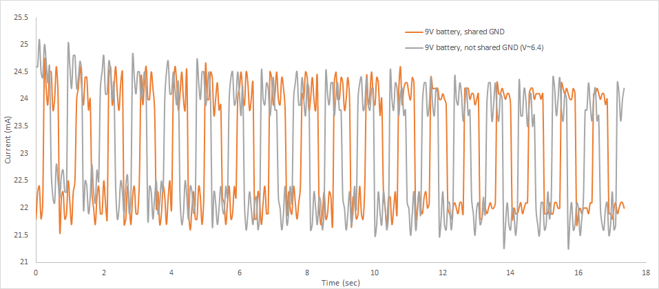
I tried hooking up an Arduino Nano with a 9V battery running a simple blink sketch, and measured the current draw. I wired it using a common ground as my schematic suggests, and also wired it with the 9V battery's GND going directly to the Arduino (and not being shared with the INA219 GND). According to the plot I made, the current values are pretty much the same despite the slight shift in the time axis since I didn't synchronize the graphs. But the major difference is that using a common ground allowed me to read the voltage in real-time as well. Otherwise, I had to switch the contacts of the INA219 (move the wire from Vin- to the INA219 GND) to read the voltage.
What's interesting is the voltage values seem to differ. When using the common gnd, I was reading voltages of about 6.15V. When using the other method, I was reading ~6.4V. Why would this be the case? The open-circuit voltage of the battery when hooking it up to a multimeter is approx. 6.75V
9volt battery as in smoke alarm battery.
They can't provide a lot of curent, and voltage will sag more and more under load as time goes on.
A blinking LED could make battery voltage hop up and down, something your DMM will largely ignore.
6.15/6.4volt from a primary 9volt block battery means the battery is already dead.
Note that the INA219 measures voltage on the +input only.
Leo..
Hello. I have a question about this INA219. My design is to be able to read very precise current for up to 100 DCV.
I found an article for this module and said that the V- and V+ current sense could also be connected to lower potential side of the circuit. And I'm planning to connect the V- sense to its ground pin.