Hello there, my team and I have been using the VCP Monitor 4 click to read power, voltage, and current and I was testing it on an Arduino Mega 2560 R3. Ideally, I want to move this to the Teensy board, but that might be a question for the Teensy Forum. But for now for some reason when I read the manufactures ID, it will only read it correctly when the gnd pin is not connected. It gets 5v from the Arduino board. Is there something I am missing or assuming that is wrong?
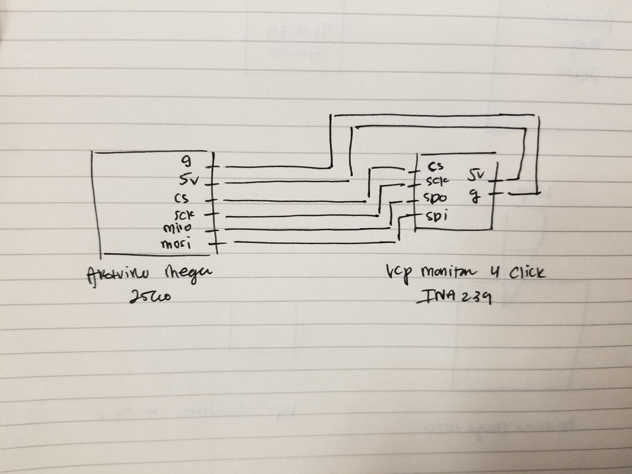
Please post a hand drawn wiring diagram, with pin numbers and parts clearly designated. Include the power and load connections being monitored. There is something seriously wrong.
I have no load on it currently. I can add a resistor and LED onto it for 3 volts but for now I am checking it by verifying that it can read out its manufacture ID which is stored in Register 0x3E based on the datasheet. This is the simplest to test the power sensor. The wiring diagram I have is also very simple SPI connection. Keep in mind that when I have the gnd pin connected it reads 0, but when I have it detached it reads the ID correctly. The ID is 8473 (ASCII) which is TI (char).
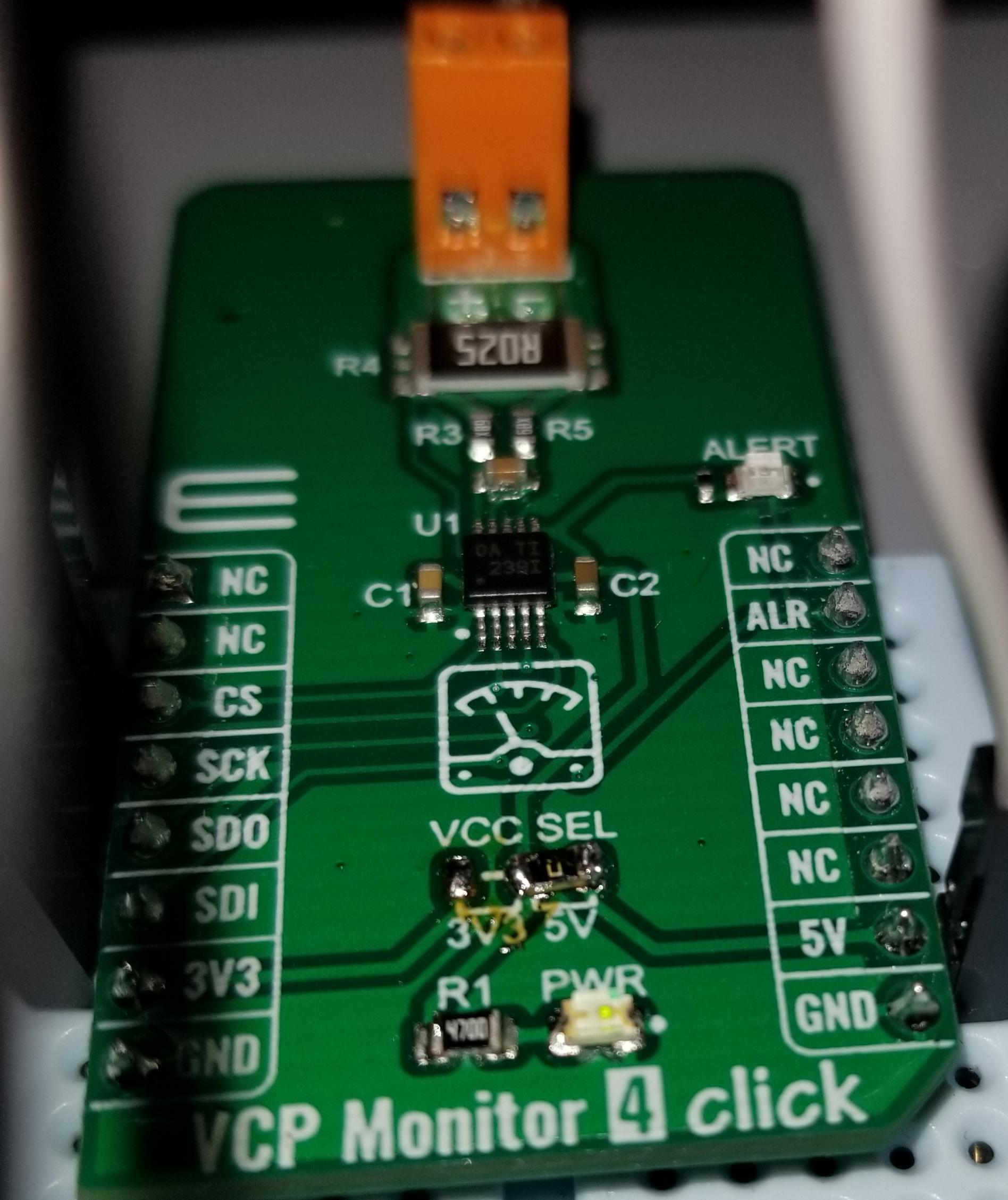
The VCP_Monitor_4 schematic shows that there is a jumper (JP1) for Vcc selection but In the picture it shows a zero ohm resistor soldered on the 3.3V side of a smd jumper.
It is simply incomprehensible how that could work without a ground connection.
Something else must be substituting for the ground reference, like the /CS connection. Which suggests a PCB fault, solder bridge, etc. Post a close up, focused photo of your soldering.
I would go around and touch up those joints, especially 5V and GND. You have several cold solder joints.
The jumper does not look good, as well. There is no need to keep it, as it is easier to solder a thin piece of wire across the gap, or just use a solder blob.
Inspect all connections with a magnifying glass for shorts, and use a brush with rubbing alcohol to clean off the rosin.
Sparkfun and Adafruit have excellent soldering tutorials, and this is a handy guide:
Hi everyone. I took a break from messing around with this power analyzer but now I am back at it. Perhaps a bit more information I collected could help you guys help me
Below I list my two issues with this device.
The vcp monitor 4 click works w/out the ground pin connected. I also have multiples of this device, and they all behave very similarly. I did some digging and believed this is due to the supply power (3.3/5V) bypassing the esd diodes in the IC when the ground pin is not connected, thus grounding through the data pins back to the Arduino controller. So, it works both ways but reads data correctly when the ground pin is not connected. Also, I was thinking that the breadboard could be a factor because initially I had the device in a breadboard and when I took it off, it was reading correctly with the ground pin connected directly. But if you guys have other suggestions feel free to explain.
The spi communication does not read or work pass a couple inches. I tried different length wires for the communication (4", 10", 18", and 24") and only the 4" wire works. I then tested another spi communication device for measuring temperature MAX31865 with the same wire lengths and it works.
It sounds like the issue is the MIKRO vcp monitor 4 click which uses the ina239 IC. I don't want to move away from this since it would be a great power analzyer for my application. The highest voltage reading is roughly 60Vdc and current reading is roughly 20A.
I am also open to alternatives that can work with the Arduino boards as well if they can handle the voltage and current specs I am after.