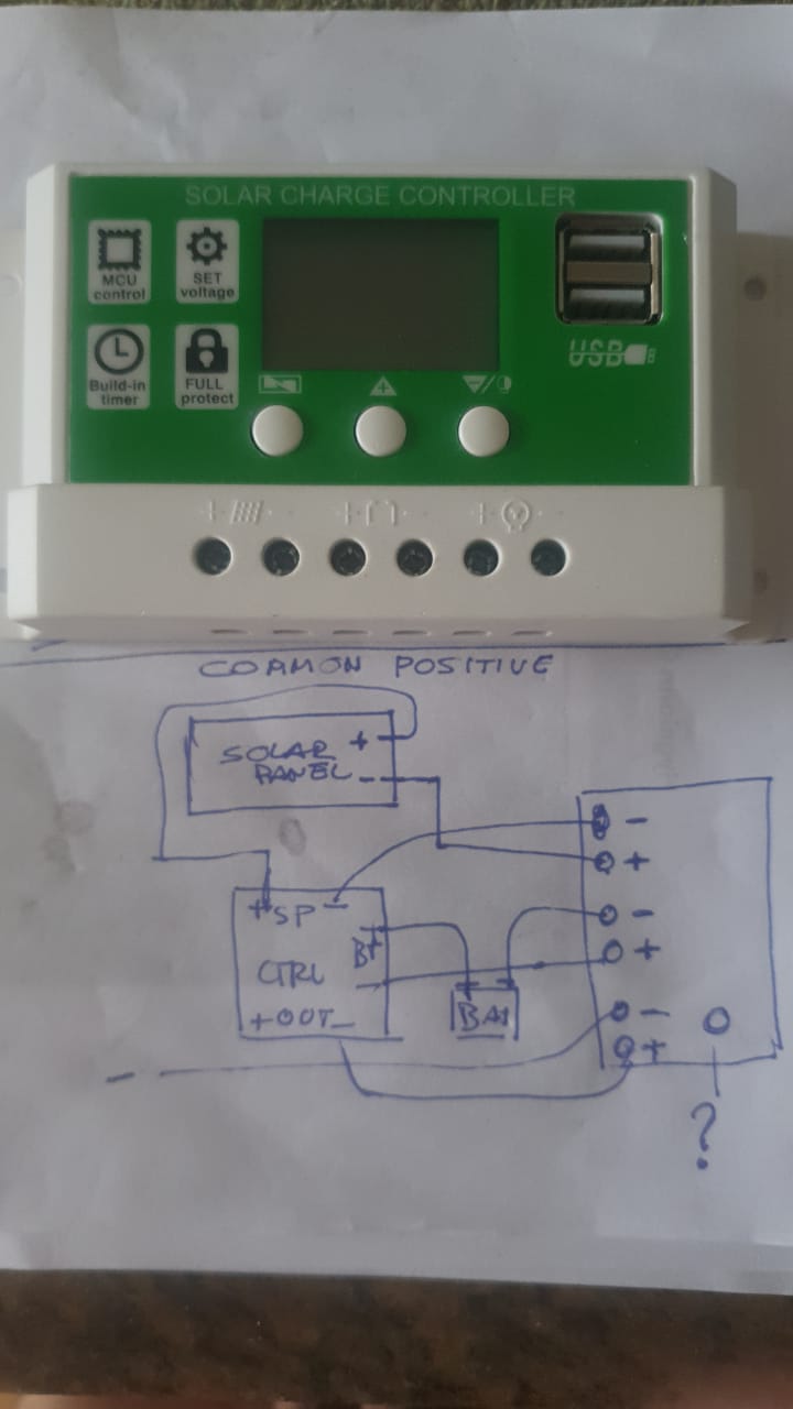
Bad idea. Common positive is good.
Just connect the common(s) of the INA to one (or more) of the + connections of the regulator. And the (+)battery/panel/load to the three current terminals of the INA.
These solar regulators regulate in the ground wire, which means a solar panel can go several volts negative, which will burn the INA.
Leo..
Thanks for the aswer. But i didn't get "connect the common(s) of the INA to one (or more) of the + connections of the regulator. And the (+)battery/panel/load to the three current terminals of the INA." Could you please clarify?
I believe @Wawa is in New Zealand, time there is 02:27 (2:27 AM), pretty sure he will drop by a little later.
PS: I'm not familiar enough with INA3221 to help.
You said that your solar regulator has the positives in common (joined together inside the box). That is correct. I have the same one on my desk here. So the three + terminals of that regulator could have been a single + terminal. They just used six for user convenience.
If you would have bought the more common INA3221, with joined channels, then you could have used a single wire between one of the + terminals of the regulator and the common shunt terminal of the INA.
You can of course use the INA you have, with three wires between the three + terminals of the regulator and the three + shunt inputs of the INA. Your panel/battery/load positives must now go to the three negative shunt inputs of the INA.
If current of one channel reads with the wrong polarity, then swap the + and - of one INA channel (you can only do that with your "uncommon" INA). Others have to do that in software.
Leo..
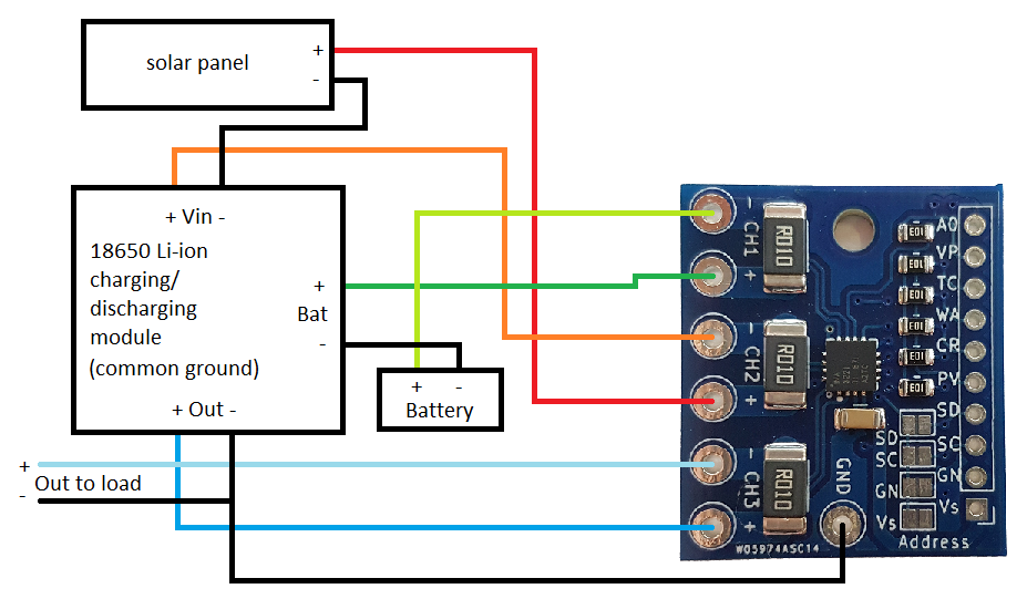
Seems ok, but I assume you would get power/ground for the Arduino and INA board from the USB socket of the charge controller, not the ground as you have drawn from the load(-).
Leo..
No, the three grounds are all different.
Load ground is connected to battery ground with a mosfet switch, for overload protection.
Battery ground is connected to controller ground and ground of the the USB sockets.
Solar ground is a whole different story. Don't use.
I think it makes not much difference if you use load ground or battery ground. I would prefer battery ground (USB sockets), because I also would want to know accurate battery voltage, not load voltage.
The USB sockets do have an efficient switching 5volt buck converter.
Makes sense to use that.
Leo..
@Wawa , Thank you, but not that easy. The meteo station runs an ESP32, but wind direction and wind speed meter runs on 12V, and some other sensors (most I2C), like light, dust, etc, which drains more than the ESP32 can supply. So i feed the whole circuit with 12V, which feeds (3V3 and 5V) directly the sensors and the nodemcu 32.
That's why i need to run it from the controller output (12V)).