Sorry, my fault. I completely missed the part about photodiodes, I was thinking only LEDs 
I am not sure.
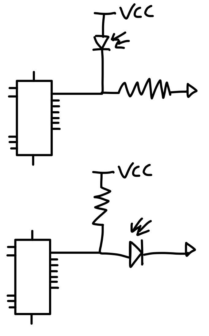
I think you will need to power the photodiode and resistor like:
VCC ---> resistor ----> photodiode ----> GND.
Then connect the input pin to one or the other end of the resistor.
You will need to check to see what the voltage drop is across the photodiode. That is, when the photodiode is on, and if that is low enough for the HC165 to read as a LOW.
470 ohms would normally be too low a value for biasing a photodiode. Also unless you are using them in photovoltaic mode, they should be reverse biased.
Actually you should put down the design until you research the difference between photovoltaic and photoconductive modes of a photo diode.
i will use Photoconductive mode, i did research.
Great. Do you consider the problem solved now?
I'm not sure, I guess I should try
because not connecting to mcu will connect to 74hc165
If you're not sure, design it and post the new schematic.
That isn't photoconductive mode. All you did is add bypass capacitors. Go back and research some more. Are you doing any bench experiments with actual components, as you design this? You should.
Also please pay attention to advice. I told you 470 ohms was too low a resistance value, you changed it to 220 ohms which is even lower.
The exact correct circuit has already been detailed in posts #63 and #64. Please make an attempt at following it.
Or else, use photovoltaic mode and explain to us what problems are remaining, if there are any.
So can you make me an example? This issue confused me a lot. Can you make an example like your message in #64?
I want to do this, let the photodiode be 1 when the infrared ray comes, and 0 if there is no ray, I will connect it to the digital pin input of the arduino, you can think like this.The photo diode model in the schematic is not important, I can replace it with the appropriate one.
You don't need capacitors on the VCC line.
Each input should be pulled high with a resistor, and pulled low with a photodiode. or the other way around. Doesn't matter.
Depend on whether your photodiode is photo-conduct or photo-resist it will be either low when there is a lot of light or when there is no light.
I recommend getting some photodiodes and find resistances that are adequate, then find resistors that pair with them well.
The resistor must have at least 2x greater (resistance) than the photodiode when it's considered "on". And the photodiode must be at least 2x greater resistance than the resistor when it's considered "off".
Depend on whether your photodiode is photo-conduct or photo-resist
Photodiodes don't differ in that way. It's the circuit that determines the mode. They might be optimized for one or the other, though.
You have drawn a photodiode. It's a phototransistor. Circuit is correct, not the symbol.
A photodiode should be reverse biased in the photoconductive mode you've shown. So a true photodiode wouldn't work well in that configuration
what do you think about that

Not sure that the 100nF capacitor is needed. What is the reason for it?
Have you had a chance to experiment with your phototransistors yet?
You might want to look at this too:
https://learn.parallax.com/tutorials/robot/shield-bot/robotics-board-education-shield-arduino/chapter-6-light-sensitive-11
no, I haven't had a chance to try it, what I want is that when the infrared light comes on, it doesn't matter whether it is high or low, I want it to work like a button, I want to connect it to the digital input, not the analog input.
The circuit looks good, with out the capacitor. I would recommend experimenting with the values of the resistor, unless you have the data sheet for the photo transistor.