Hello
I've been working on a project but no success. Any help would be really appreciated.
I am trying to build a device to convert a completely manual laboratory process to an automated one.
8 channels monitoring fermentation in 8 bottles. Each bottle is connected to a glass tube which is slotted. In that slot I placed BMP 280 for each channel connected to a TCA9548A multiplexer to record the pressure. The pressure in first steps are recorded and their average is registered as reference for future. When the pressure reaches a threshold, my Arduino mega2560 sends a signal to the relay for each channel and opens an electric valve and the pressure goes back to normal. The loop repeats.
Everything is alright except almost nothing. Bmp280s report varied numbers which regardless of my altitude from sea level, are irrelevant to each other. For example they report 881.0 and 1071 in the very same loop in a distance less than 30cm on my table!!! I don't really care about their numbers because I only want the difference from the reference pressure which I explained before. But the problem is they are not reliable too. In every 4 or 5 times that I start the device, at least 3 of them won't even connect, if I try to reset them to others also reset. Sometimes they don't even read. I should reset them to work again. Correcting all these flaws took me hours to write the code but still no success.
Do you think I chose the wrong kind of sensors? Do you have any suggestions for me to replace them with something else? Has anyone heard such problems from BMP 280 before? Any solution?
My code comes below. most of its complicated look was due to trying to correct all the malfunctions I found during millions of times tests!!! but still they exist
There is probably something wrong with your hardware or software. Which, we can't see.
Probably, nobody else is going to jump in, who has also put BMP 280s in 8 flasks. So you're depending on people to perform an analysis. For that you have to provide information.
Thank you very much, I tried this settings in different modes, Norma and forced. But they did not help a lot, they even fried one of my sensors (I don't know why!!!).
Since you're using an Arduino Mega I guess you're powering the TCA9548A with 5V, but are you using 5V to 3.3V I2C level shifters on your BMP280 breakout boards?
Sometimes these boards come with level shifting built-in, sometimes not.
Do you give each 280 time to respond before switching to the next.
In fact when you switch, do you give enough time for the switch to take place and connection made, then enough time for the reading to be received?
Can you please post a schematic?
You don't have to show all 8 280 connections, just 2 will do.
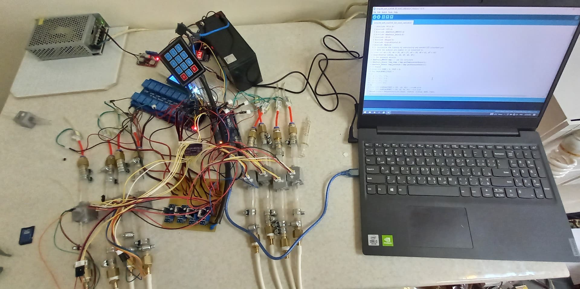
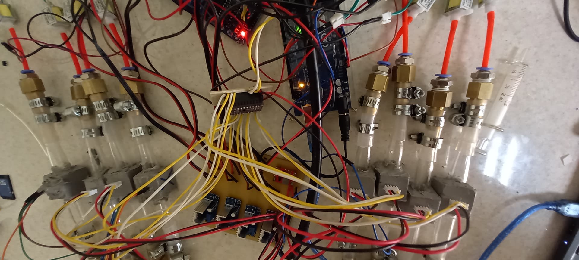
Can you please post picture(s) of your project so we can see your component layout?
I use the 3.3 v from an external power supply with a common ground to Arduino. I didn't use level shifters. Although, I tried using Arduino 5 and 3.3v supply too but no difference. Actually when I used 3.3 volts I encountered limited mAmps for all the sensors and TCA9548A, this made me use an external power supply.
Hi,
Do have pullup resistors on the SDA and SCL lines, I'm not sure but the 9548 doesn't have them.
If you are using a module they may be fitted already.
Have you a 9548 module/breakout board, or just the IC?
@MartinL
these are a clone exactly equal to the one which Adafruit provides. And also yes I know their current requirements are not too high, but during all my efforts I tried to replace any tiny suspicion I had, and this was one of them. Anyhow, it still does not work!
The BMP280 is very accurate and reliable and it uses almost no current.
You have to know what the hardware and software is doing, that means taking a few steps back. We also need a lot more information.
First of all, forget about your project. You will have to test the sensors one by one.
Can you give a link to where you bought the sensors and the I2C multiplexer ?
Do you have a 3.3V Arduino board ?
The sensors are 3.3V sensors and the Arduino Mega 2560 has a 5V I2C bus with 10k pullups to 5V. That can damage the sensors, don't connect the bare sensors directly to the Mega board.
The I2C multiplexer can do I2C voltage level shifting (power it with 3.3V).
The I2C bus has three wires: SDA, SCL, GND. I can not clearly see where the black GND wire is going.
In the sketch, each sensor needs its own object. I only see one 'bmp' object.
Suppose you finally can get all sensors working, then you can add the valves and maybe you have to start all over again if that disturbs the I2C bus too much.
Dear Koepel;
Thanks for your response.
I bought sensors from a local store but they are exactly like this: BMP280
As you mentioned I use Arduino mega2560 but the TCA9548 connected to I2C bus is connected to a 3.3 v supply, so are the sensors. doesn't it do the job?
The GND goes to the power supply and all the GNDs are connected to the Arduino GND. Also Arduino power is supplied by the same source but different voltage regulator (9volts).
I assumed the code would call the bmp for each individual sensor and takes that as a separate object.
I will be happy to give you any other info that could help.
@mhm-k The BMP280 is a 3.3V device that isn't 5V tolerant. If the BMP280 breakouts don't have level shifting then you'll need to use an addtional I2C level shifter, in order to protect each board, such as this 4-channel one from Adafruit: https://www.adafruit.com/product/757, (other level-shifters are available).
Each 4-channel level shifter can be used to level shift two breakout boards, just connect the 5V pin of your Mega to the higher voltage (HV) side and 3.3V to the lower voltage (LV), as well as ground. The HV side can be used to connect the 5V SCL and SDA from the TCA9548A, while on the LV side the 3.3V signals and power go to the sensor breakout(s).