Hi,
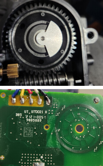
I have this inductive rotary sensor with printed coil on PCB. It has three pinouts - Vcc, GND and Out.
Unfortunately I don't have any datasheet for this product.
When connecting 5V and GND to respective pins, I measure about 3.4-3.5V across Out and GND pins. This value doesn't change when the metallic semi circle disc is rotated over the coil.
I never used such sensor previously and would be thankful if someone can assist me in getting the output right.
Thanks.
Z
I was measuring the out voltage using a multimeter.
Can you supply a photograph of this sensor please.
Thanks, not seen that sort of sensor before.
How did you know what wires were 5V and ground?
Most inductive sensors work on current draw. That is there is more current draw from a coil close to metal than not close to the metal. I did expect the disc however to that shape.
There will be an oscillator somewhere and an AC signal will be being generated. Close proximity to the metal will stop it from oscillating.
I would say from the PCB pattern that it will not give you anymore resolution than 12 different readings per circle so that would be 360˚ / 12 = 30˚ resolution.
However the connectors going from the sensor once you account for power and ground are only three. This implies that you might only get 8 possible readings and therefore only 45˚ resolution.
What I would try is to connect the three signal outputs to ground, through a resistor and measure the voltage across the resistor. As to the resistor value you will have to experiment, I would start off with 10K, and go either way doubling and halving the values between 510R and 100K.
Again how do you know what wires are 5V and ground, and what makes you think it is 5V and not higher? Most "normal" inductive proximity sensors I have use are powered by 12 or 24V.
Thanks @Grumpy_Mike
Those Vcc, GND and Out pins were indicated by seller but he wouldn't provide more information.
I have tried 12V as well but output voltage doesn't change when I rotate the disc.
I am not sure I understood the resistor connection you mentioned.
Do you mean to attach 10K across Out and GND pins?
Consider asking the seller for more information, or post a link to the product page.
@jremington
I wish.
Its an automotive part. Local seller has no idea how do I read the data nor any information is available online.
You need to scope the OUT lead while spinning the reluctor at a steady, reasonable clip (VSR drill or drill press). Guess is you'll get a PWM pulse train. What exact (year/make/model) vehicle is it out of?
The vehicle service manual should list a field test procedure and circuit.
No. I said:-
through a resistor. That means, signal output -> resistor -> ground.
Then measure between the junction of the resistor with the signal output and ground.
Note this is not across output and ground as you mistook it to mean.
@Grumpy_Mike
Is this you meant?

With only three outputs there means there can only be a maximum of 8 different combinations of outputs. Two to the power of three is eight.
@Grumpy_Mike Yes that's correct but two pins out of three have 5/12V and GND which are fixed.
Thermostat water pump? The description says its mechanical. I can't see where that pcb could fit. WHY are you bodging up this part? What are you trying to do? How/why did you select THIS part?
No that is two pins out of five. I counted five wires going into that board on the photograph you posted.
Two orthogonal coils with a center tap? Sorta like a stepper motor in reverse. Phase shift gives relative angle. It may require a "exciter" signal.
@Grumpy_Mike Other two pins are M+ and M- for controlling the motor.