Input protection for a ground sensing input

Hi all,

I'm designing a small box that translates various input from my car into CAN bus to send around the car. One particular one is a ground pulse. When I operate my remote trunk release, the central locking unit will pulse one of its pins to ground, which would normally be connected to a 12v relay to activate a solenoid. In my case I want my arduino to spot this ground pulse and send a CAN message.

My question relates to input pin protection. I was going to simply connect one pin to the other, and use the input_pullup function on my Teensy 3.5 to detect when the pulse is triggered. Since very little will be travelling down this line, do I need any protective circuitry, if so what should I put on there?

"ground-pulse" is a somewhat akward description.

The other end of the solenoids coils would be connected to +12V permanently to make this work.

What your microcontroller can do is measuring voltages in relation to the GND-"contact" of the microcontroller.

Simply connecting this contact that closes a switch to establisch connection to the minus-terminal of the battery alone won't work.

Please post a schematic of the original wiring with the relay
and do measurings with a digital multimeter.
Black wire connected to minus-terminal of the carbattery red wire connected to the switched pin. And then make it switching.

What kind of input-protection is required highly depends on what the circuitry is really wired. If you don't have a real understanding of what is going on there is a pretty high danger of frying your Teensy 3.5 with 12V !

"Ground-Signal" indicates that you are not really familiar with electronics. All electronic hobbyist and professional will do a careful analysis of the wiring and the occuring voltages.

best regards Stefan

Thanks for the response Stefan, indeed I'm a mechanical engineer not an electrical one so sparks are a little bit like black magic :slight_smile:

The car isn't built at the moment, it's in many pieces in a different country, but I'm developing some parts for the build later on. The circuit I'm referring to is this one: AUTOWATCH 457 RLI WIRING DIAGRAM Pdf Download | ManualsLib

If you look toward the bottom-right of the diagram, you'll see the trunk release function. As it describes, in normal operation you would connect an ignition controlled 12v feed to a relay coil, with the other end feeding back to the Autowatch device through the blue/grey wire.

I will be controlling the trunk release solenoid via a solid state power distribution unit, and that unit has a limited number of wired inputs, but as many as you like when using CAN bus, so I'm building a small unit that converts several inputs into CAN bus for use on this circuit and others. Most circuits use 12v switching, so I am using opto-isolators to give the teensy a nice safe switched input, decoupled from the car circuit.

I could use an opto-isolator on this circuit except I have 2 problems, the first is that this board does not have 12v available on it, since I don't need it for anything else. I do have 5v, so I could run 5v to an opto isolator via a resistor, then grounding to this blue/grey wire on the autowatch unit. The other problem is that I'm trying to keep this board as small as possible and fitting another opto-isolator on there is going to be a challenge so it would be better if I could avoid doing so.

So essentially at the moment, my idea is to connect the teensy 3.5 input pin directly to the blue/grey wire on the autowatch unit, and using the input_pullup function I should be able to detect when the trunk release is activated by treating it as just a switch to ground.

12V comes from the car and it's on the "car side" of the opto-isolator. :wink:

Or, you can make a protection circuit with a diode & resistor. (In this application I recommend a higher-value resistor, maybe 10K.)

And with the Arduino you need to add another "pull down" resistor between the Arduino input and ground to keep the input from "floating up". The two resistors make a voltage divider so with ~12V they resistors can be equal value.

Thanks Doug, on the 12v front, I mean I have a 34 pin IDC socket on the PCB and I'm using every pin. The next size up is I think 40 pins and I don't have room for it.

On another board I have a switch that is connected between an arduino pin and ground and I can detect it's state no problem without any resistors. Would the same approach not work here? In terms of the basic concept of detecting the trunk release event before adding any circuit protection I mean.

Hi Nick,

thank you for providing the download-link to the manual.
You have posted a worded description how things are wired.
I'm very unsure if I understand it right. I will not read your description 20 to 50 times
trying to interpret things right by guessings and assumptions.

The reason is: If you provide two freehand-drawings that has names on it and shows which component is connected to what;
everything will be clear by taking a few looks on this schematic. It doesn't have to be looking beautiful or professional the information counts.

So this schematic should show

to what other component of the car is connected

connector 85, 86 (the coil of the relay) ?

connector 30, 87a, 87 ? (the switching contacts of the relay)

drawing 1 showing how things are wired originally

drawing 2 showing how things are wired with your modifications.

best regards Stefan

Hi Nick. It's you again with the car of your dream. :slight_smile:
I see you still have to read Protecting Inputs in Digital Electronics.:slight_smile:
Using an optocoupler is a good idea. In this case, you do not have to protect the inputs of the controller. The scheme is known, for example, Optocoupler for Switching DC Circuit
Optocoupler-for-Switching-DC-Circuit
If you want to use a voltage divider, keep the following in mind. The voltage in the car network can reach 14.4-14.6V, and even more. You must take this into account when choosing the divider resistances. In this case, it is imperative to protect the controller inputs with resistor, diodes and capacitors as in case of fuel sender.

1 Like

Hi there Boffin! Indeed I am still on my quest :slight_smile:

I have read the material, and every other input I have protected, but this one seems different to me... Perhaps this thread will reveal that it isn't, let's see!

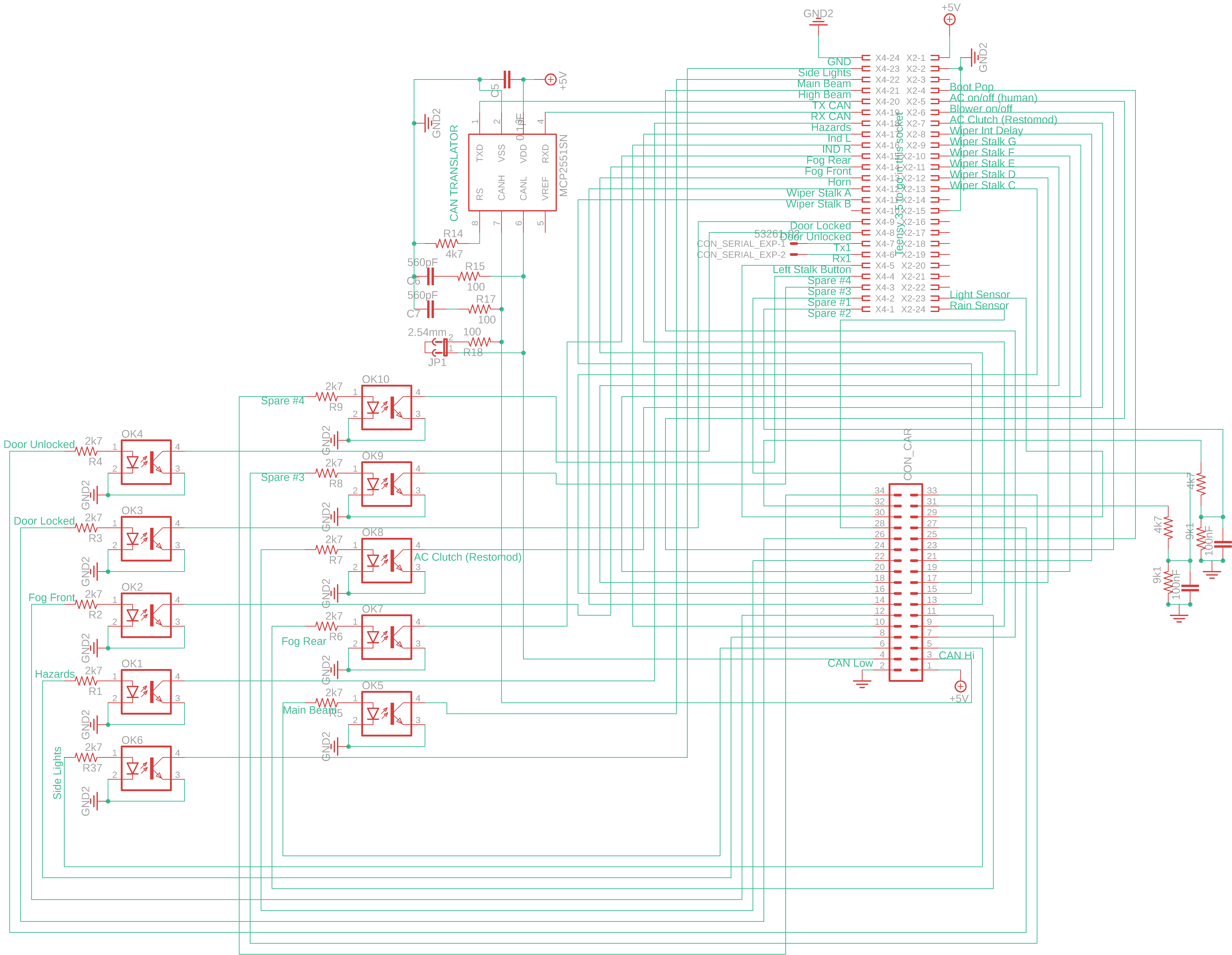
Ok so some more background... Here is my little CAN Translator board as it stands today:

It's pretty simple, basically just an IDC connector onto the board for 5v and GND from a close by board with a 5v dc-dc regulator on it, then it has a small CAN transceiver arrangement for the CAN bus, a 3.5 Teensy and a a bunch of opto-isolators to monitor the switch states of various things like lights, indicators etc.

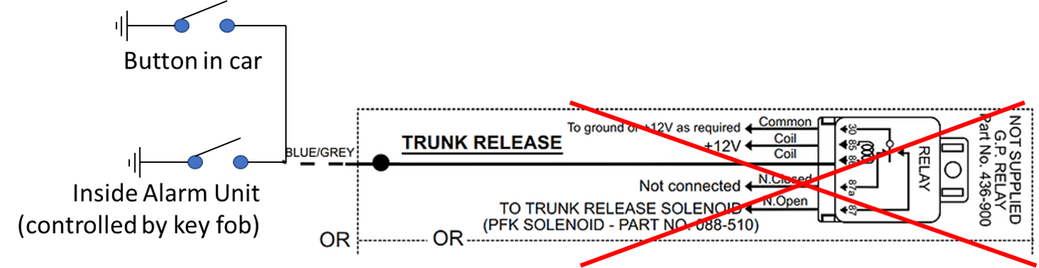
The trunk release is different (to me) because the circuit is just a switch to ground. There is nothing on the car right now and the loom I'm designing is totally bespoke. I will use an alarm system like this Autowatch one, which will control trunk release. To do that, I will use my PDU to control the solenoid side of the circuit, but it needs to know when to operate and for that I need the control input which will come from either a button under the dash, or the alarm system switching to ground.

So to be clear, this part of the circuit goes in the bin - I'm not using any relays in the car build at all (at least that's the goal!), leaving me with this:

From here there are a few options... Here's 3 that I can see...

Option 1 would just use a resistor to the 3.3v pin from the teensy, so I could use input_pulldown to determine when the trunk release is activated


Option 2 would use an opto-isolator. I only have 5v available on this PCB so this would be used to drive the isolator with a resistor. I'd use input_pullup to read the state of the input. The downside with this one is I don't have much space on the PCB to include this extra isolator and resistor


Option 3 would be to just use input_pullup to read the state of the input, with a set of protection diodes to prevent any spikes picked up in the long wire between the units. I'm unsure if this would need a resistor/cap as well since the signal would be tiny from the teensy internal pullup.

What do you reckon the best route is, with simplicity in mind to keep the board small..?

[EDIT] - I think actually for my purposes, option 2 looks to be the best solution so I've tried to squeeze it onto the board and it looks like I can just about do it...

This topic was automatically closed 120 days after the last reply. New replies are no longer allowed.