Hi all! I'm new to microcontrollers, but I finally made the plunge a few weeks ago to pursue my longterm goal of creating a personally designed tamagotchi-style device. The purpose of the project is to learn, and I anticipated a lot of difficulties, but I'm concerned my entire approach might be wrong and I would appreciate feedback.
I have basic experience with python and Lua and with teaching myself coding through projects. My plan, therefore, was to first identify the device I wanted to use, set up the buttons and screen, then focus on the software side entirely before maybe one day actually 3D printing a case and figuring out how batteries work.
I decided on the Seeed Xiao RP2040 because it's the only board that seems small enough to even get close to an actual tamagotchi size, and it seems like it has.a relatively high degree of compatibility with the Arduino and Pi Pico ecosystems. I'm worried this has been a mistake.
I'm finding that troubleshooting even basic aspects of the setup process is incredibly difficult without the large beginner user base of something like the Pi Pico or Arduino nano, especially given the small idiosyncrasies of a product like the Seeed Xiao RP2040. I can't even get the Seeed-manufactured ssd1315 oled display working. After hours of troubleshooting it seems impossible to tell without an active user forum whether the problem is me, the screen, the wiring, or the Seeed Xiao itself.
I feel like I might just be too new to this to use anything but a very mainstream board, but I'm also concerned that if I create a program for something like the Pi Pico, I'll never be able to figure out how to convert the program for something that could actually fit in the form factor I want.
I really just want to get started learning the software side of things, and I never imagined it would be this hard to get a prototyping board set up. Am I being dumb not just buying a simpler board, or is this going to be my experience no matter what I start with?
Any suggestions or comments on my approach would be appreciated.
What difficulties have you had getting the screen to work ? Which library are you using and does it come with any examples ? Are you getting errors when you compile the code ?
Please post a test sketch, using code tags when you do, a schematic of your project, a photo of a pencil and paper drawing is good enough, and the full text of any error messages that you get. Turn on verbose reporting in IDE Preferences first
Beginners almost invariably underestimate how difficult it is to get started on a new technical subject. In fact, there is a name for this well studied phenomenon: the "Dunning-Kruger effect".
Adafruit has the very best overall system of well-designed starter boards, "getting started" guides and projects.
Seeed Studio is one of the worst places to start, as most of the material posted is simply copied from other sources.
I appreciate the offer of help with the screen and would take any advice, but I've kindof given up on using Arduino in favor of micro python (at least to prove the screen works) because I don't have the skills to troubleshoot using Arduino. However, the info requested:
When using the code below, there are no compile errors and the code uploads successfully. Then, nothing happens. The screen does not turn on, flicker, or give any other indication that it is being accessed. The power light on the board is on, as it always is when plugged in. [Using similar micro python code and Thonny, I was able to confirm that the I2C address of the Oled screen was recognized correctly using the i2c.scan() function, but that any "write" commands in the code resulting a timeout error].
I am using the U8g2lib. I don't know that it comes with any examples. I am using ArduinoIDE with the settings for the Raspberry Pi Pico/RP2040 Board. These settings and code come from a guide provided by Seeeed, the board manufacturer.
I am on OSX; Arduino IDE does not have a "preferences" menu I can find and the "settings" menu does not have a "verbose reporting" checkbox.
Sketch:
#include <U8g2lib.h>

#ifdef U8X8_HAVE_HW_SPI
#include <SPI.h>
#endif
#ifdef U8X8_HAVE_HW_I2C
#include <Wire.h>
#endif

U8G2_SSD1306_128X64_NONAME_F_SW_I2C u8g2(U8G2_R0, /* clock=*/ SCL, /* data=*/ SDA, /* reset=*/ U8X8_PIN_NONE);

void setup(void) {
  u8g2.begin();
}

void loop(void) {
  u8g2.clearBuffer();                   // clear the internal memory
  u8g2.setFont(u8g2_font_ncenB08_tr);   // choose a suitable font
  u8g2.drawStr(0,10,"Hello Wrold!");    // write something to the internal memory
  u8g2.drawStr(0,30,"Hello Werold!");
  u8g2.drawStr(0,50,"Hello Wrrrold!");
  u8g2.sendBuffer();                    // transfer internal memory to the display
  delay(1000);
}
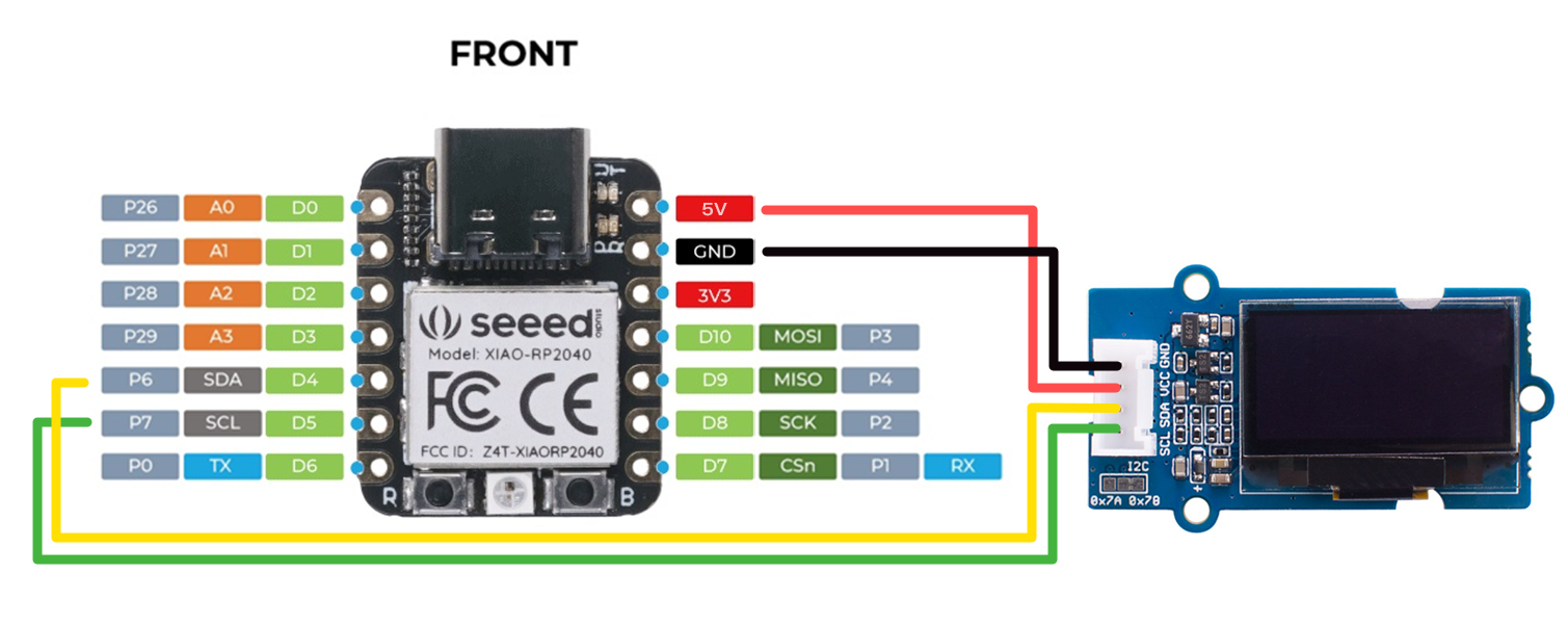
Schematic (identical to image from manufacturer provided here):
This gibberish is the most I could get the screen to display (using micro python):

Look under File in the IDE menu
Sorry to double-reply, but I see now that I should include an upload of the schematic instead of a link for convenience:
Is the IDE menu something other than this?
Which version of the Arduino IDE is that ?
Sorry, I should have included that: it's 2.3.2
I have no idea what a tamagotchi is, but your post prompted me to try my RPi pico with an OLED. Mine has CircuitPython installed and I found out that the link I posted is actually for Micropython, not CircuitPython so it didn't work for me. I don't know what's on your Seeed board though.
I was finally able to get the OLED demo to work with CircuitPython, but it took a bit of digging.
First, I downloaded the displayio and board libraries: CircuitPython Setup | Adafruit OLED FeatherWing | Adafruit Learning System and followed the instructions to copy the lib files to the RPi Pico
Next, I uploaded the SSD1306 code in the examples folder: displayio_ssd1306_simpletest.py (rename it to code.py to run on startup) but it didn't work. Turns out you have to modify this line
i2c = board.I2C() # uses board.SCL and board.SDA
to
i2c = busio.I2C(board.GP1, board.GP0)
then it works!
It's not easy starting out with poorly supported hardware, but hopefully this will get you going. CircuitPython is very popular so it should be easy to find examples when you get stuck again.
[edit]
One thing I meant to add is that be sure that the address is correct. For the SSD1306 it's commonly 0x3C or 0x3D. It looks like you board is using 0x7A or 0x70 and I don't see anything in your code that refers to a changed address!
Thanks for the suggestion! I was using micro python because the manufacturer (of both the board and the Oled) has a tutorial for micro python but not for circuit python. However, I may give that a try next.
I don't think the address is the issue. On micro python, sending the serial scan i2c.scan() after setting up an i2C connection returns the address [60] (iff the Oled is properly connected), which I understand to be x3C. Changing x3C to x3D in the code also gives a EIO error (which I understand means no hardware connection; this error also appears if the Oled isn't connected at all). This says to me that x3C is the right address.
Found it! Preferences is called "settings" in OSX, and I found the verbose output checkbox in settings. I will compile again and send an update later.
However, would I be correct in thinking this will only identify compile errors, and not give any hints at issues occurring when the sketch is running?
Thanks! I tried this, and it actually doesn't apply here.
It looks like some but actually not all ssd1315 OLEDs use address x3D. Grove, the oled manufacturer, implicitly mentions this issue by noting somewhere on the product page that their current ssd1315 boards (including mine) use x3C address to maintain compatibility with ssd1306 libraries. I have confirmed that the address on mine is x3C.
Yes.
But keep the serial window open while the code is running so you can see if it's crashing at runtime.
I tried this without thinking it would work (so I didn't try it repeatedly) and didn't see anything. So an Arduino sketch will send crash data over serial even if a serial connection isn't part of the sketch? If I can make that work that would be a huge help.
It will also show warnings of some things that will still allow the code to compile but could cause problems when the code runs. It will also show exactly which library files have been used should there be some where multiple copies are available
It may not help diagnose what is going wrong but can be helpful
A "regular" Arduino C++ program won't, but a Python program will.
Let's take a deep breath and a step back. I think first we need to understand exactly what's running on the board. I referenced Python because you said that you had given up on the Arduino IDE and decided on micropython. But if you are running the code shown above, then everything I said about Python should be ignored and the only relevant thing is the address, which you've confirmed is correct.
So, if the above program is the one that you're running, the first thing that I'd want to do is confirm the values of SDA and SCL above and make sure that those pin #'s are indeed the ones that you have your display connected to.


