Looks great! My main use for something like this would be Insteon, however it'd be really cool to see how it could be used for a variety of applications. Quick question, does this include its own 8P8C connector or does it interface with the one on the Arduino Ethernet? If it has its own connector, would this make it compatible with simpler Arduinos like the Uno?
Yes, the shield does have it's own 8P8C/RJ45 jack, but that will be used to connect to the Insteon modem, so it's not ethernet capable. But yes, this should mean that the shield can be put atop pretty much any arduino (Uno and others).
I'm just focused on getting this working with the Arduino Board Ethernet in particular because it feels like Internet connectivity is a must-have feature for many home automation controllers... and communications with other web servers offers some really interesting possibilities as well.
Alan
Ah, thanks for the clarification.
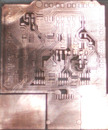
Now have a few new versions of the PCB, and all the traces are looking good. And I've attached an image of one of them:
Next step is to populate it with components for testing. I'm reasonably confident the Insteon jack will work, but the other features will require a bit more testing.
Alan
Very nice! Can't wait to see it in action.
Just a quick note to update on progress. The first couple of PCBs are completely assembled now! I've done some testing and looks like some minor soldering glitches (note to self: next time make bigger spacing and traces). There's one problem with the circuit itself that'll prevent the PGM reading feature from working on this version (this is useful for reading status from security alarm systems). But the other features appear to be working. So this board can:
- Send and receive insteon commands
- Read dry contact sensors (like the contact sensors from a security alarm system, or a pulse water meter)
- Act as a dry contact sensor (using a built in relay). So you could have the arduino output to other systems that read dry contacts (Or switch LOW power DC accessories)
I've started some documentation on the controller here:
http://www.goodrobot.com/wiki/doku.php/wiki/arduinoinsteoncontroller
Two other areas that I'm making good progress on too:
- I am very close to having finished code for an arduino insteon controller that connects to the internet. Will keep you posted on that.
- In parallel I'm working on some web server capabilities that'll integrate with the controller (allowing you to do cool stuff like get alerts via automated phone alerts or SMS messages and such).
...anyone still interested in beta testing, please let me know. I'll be ready to ship the first couple of boards out to you very soon!
Exciting stuff so far! I'm very interested in beta testing one of these guys. I'll need to go and get an ArduinoBoardEthernet if I want to make full use of it.
Sorry for the prolonged absence. Good news is that I shipped the first couple boards out (for those who didn't get one, my apologies, but I have ordered more). Since then, the circuit has a few new design changes, and yesterday I placed an order for 26 PCBs of the new version. So there should be no shortage of boards this time.
Code for ArduinoBoardEthernet is finally at a stage where it's running well enough to share, and I also have an early (rough) version of a web based drag-and-drop floorplan interface too.
Tomorrow I'll spend my time sharing/documenting all that material for those interested. I'm really anxious to begin shipping these boards in larger quantities, so if you'd like to get your hands on one please do let me know.
Alan
I apologize for not replying to your PM earlier. The messaging system was down for awhile. Thanks for the updates!
Ok, I have now posted the sketch/code for the ArduinoInsteonController. With it, an Arduino Board Ethernet can act as a Web based home controller for Insteon. The code and instructions are at:
http://goodrobot.com/wiki/doku.php/wiki/insteonsketch
This version is still early (so please let me know of any bugs/issues you encounter). We should be adding new features soon (Basic Authentication and DHCP are near the top of the list).
Great stuff here! I have a whole house full of Insteon stuff, running off of a Universal Devices ISY-99.
I wish I could help out with the beta testing but I have too much on my plate right now. However the idea of interfacing an Arduino to my Insteon network sounds like something I would definitely want to play with someday.
Ideas:
-
Arduino program allowing digital and analog outputs to respond to Insteon on/off/dim/brite commands -- a nice low-voltage analog and digital IO platform...
-
Add a DTMF decoder (DTMF Shield Aimed At Ham Controlled Arduino | Hackaday) to allow me to interface a radio receiver and control my Insteon network with touch-tones from the radio in my truck
(bonus points for a Morse Code or even a voice response to the DTMF commands that were sent)
Question -- does your Arduino/Insteon solution just monitor all Insteon signals and transmit raw Insteon commands, or does it (or the PowerLinc) have to be linked to each device? I haven't played with the PowerLinc much, beyond using it with the ISY-99.
Hi Bill,
It's great to have your feedback and ideas on this.
Great idea. The terminals on the board can be connected (depending on jumper settings) to pins 5,6,7. And when acting as outputs, the same set of arduino pins can also be set off (and activate small relays). So the code to do this would be pretty easy.
I never considered analog inputs for bright/dim command, but that's an excellent idea. It might be useful to dim a light with a POT or other analog source. Nice.
That'd be quite awesome. I haven't done any work with DTMF chips before, and though it's specialized it would likely make a fun project... you could possibly mount another proto shield atop this board pretty easily in order to do the DTMF stuff. Right now we've prototyped some server side capabilities that will allow the arduino to trigger telephone voice messages - so a DTMF telephone interface (Press "# x" to turn on a light) is a natural next step.
About Morse Code... I seem to recall coming across an arduino library for this. In an older project of mine I used a telegraph key to control the motion of a robot head, might be cool to step things up and embed it into my home automation system somehow ![]()
Yes, it needs the insteon modem (just like the ISY-99) in order to communicate with the insteon devices. So I need to link it to each device, which I think the ISY-99 does too. What I like about the ISY-99 is the ability to go out and memorize the relationships of your home system and then update with new rules. It'd be nice to have that kind of capability too.
One alternative might be to use an insteon wireless chip (Insteon has one in their USB dongle) that could be mounted right to the board. That's definitely possible at scale... but in the short term, I think there's a lot of hurdles around FCC approvals and such once you go that route.
Alan
I"m happy to report that the new batch of 26 PCBs has finally arrived (see photo of new boards below). Shipping was supposed to take longer than this, so it actually beat my DigiKey order for the components.
To get these out quickly, I may make several simplified versions that don't require all the additional circuitry for relays, or PGM sensing (for DSC security alarm systems). That way it's just a jack for communicating with the Insteon modem, plus some terminals for sensing external devices through the digital pins. It shouldn't take me long to assemble those - I should manage to do that after I get my digikey order in. If things go as planned (I still need to test the new boards) I will be ready to ship out the first few at the end of next week.
In other news, there's been some great progress on the drag-and-drop web interface that will be compatible with this shield (when you use it with the Arduino Board Ethernet).
You can check it out by going to http://www.aah.ca/login (and click "register" to get started). Once you're in, head to the "configure" page to try it out. The goal is to have a visual interface that lets you drag and drop furniture and insteon controls onto a floorplan, right now basic features are working via browsers on Mac, PC, and ipad/iphone! The current version puts in a pre-rendered floorplan for you as a starting point (you can also upload your own image instead). But within the next couple of weeks we should have 10 additional "default" renderings to choose from, plus around 40 rendered objects (lights, furniture etc). You can also set up alerts and rules through the configuration page too.
The drag-and-drop feature has some (wordy) documentation describing it and the arduino setup process here:
http://www.goodrobot.com/wiki/doku.php/wiki/draganddrop

Hi All,
I've sent people out a couple more hardware shields (mostly simple versions with Insteon jack only). Please let me know if anyone else would like one to experiment with! So most of my effort lately has gone into improving the online interface at aah.ca/login/
The drag-and-drop part is mostly functional now (just working on a new feature which will put the insteon modem into link mode automatically whenever you drag a new sensor onto the floorplan).
The arduino code has also been updated since there is now a unique "access key" required for every arduino (this way the server knows to recognize the query regardless of IP address and link it to your account). You can configure your access key by going to "configuration" and clicking on the "advanced" link to enter your unique access key.
You can find the latest Arduino Insteon controller code at:
http://www.goodrobot.com/wiki/doku.php/wiki/insteonsketch
On the same page there are instructions for customizing the code to set your local IP, create a test page, and to customize your own unique Access Key.
I'll be working on additional changes next week. If anyone would like to help with coding or debugging of the latest home controller please get in touch with me here, or email me at alan@goodrobot.com
Hi All,
I've got a couple more boards ready to ship now.
Mark Wood, although I have been receiving emails from you, whenever I reply back, my email always bounces, so please let me know another email or phone number I can reach you at.
For those of you who received the shield earlier and are using it with the arduino Ethernet: we have changed the way that messages notify the server. Now each arduino must include an access key with each message passed to notify.php. This way we'll be able to accept incoming messages/events from dynamic IP addresses.
Alan
Super cool! I have a bunch of insteon devices I purchased when I purchased my house but never set anything up since I didn't buy a controller. This looks perfect, how can I get one of these boards?
Thanks! -CA
inciteman:
Super cool! I have a bunch of insteon devices I purchased when I purchased my house but never set anything up since I didn't buy a controller. This looks perfect, how can I get one of these boards?
If you send me your postal address (email me alan [at] goodrobot [dot] com ) I can build one and mail it out to you if you'd like to give it a whirl.
Alan
Id love to get one of these boards. Where can I buy one?
For those of you who have received a shield, I've updated the wiki entry about Jumper Settings (useful for those with the relay or contact sensing versions of the board). That entry can be found here: http://goodrobot.com/wiki/doku.php/wiki/jumpersettings
In addition, there's now also sample test code on the wiki that can be used for testing the most basic functions of the shield/board from an arduino (you can test these with any standard footprint arduino like an UNO): http://www.goodrobot.com/wiki/doku.php/wiki/insteonsketch
I also hope to update some other areas of the wiki too, so I'll notify the list of any major improvements or changes as well.
And in case it's helpful, here's a simple "hello world" sketch to turn an Insteon switch on and off using the shield (not pretty but it works):
// This file is an Insteon "hello world"...
// Not pretty, but may be useful for initial testing
// Before running this, you should ensure you have linked your Insteon device to your Insteon Serial modem.
// Also ensure that you substitute the Insteon switch ID's below (three hex bytes) with your own.


#include "SoftwareSerial.h"
SoftwareSerial insteonSerial(2, 3);

int inByte = 0;         // incoming serial byte
int zeroByte = 0x00;    // I use this because if I do "insteonSerial.write (0);" instead I get a compile error

void setup()
{
  // start serial port at 19200 bps (this is the speed for Insteon modem)
  insteonSerial.begin(19200);  // use software serial for pins 2 and 3 to communicate with the Insteon Modem
                               // soft serial lets us keep the arduino's serial port open for debugging if we wish
}

void loop()
{
  // if we get a valid byte, read analog ins:
  while (insteonSerial.available() > 0) {
    // get incoming byte:
    inByte = insteonSerial.read();
  }


delay (1000); // Delay for 1 second


 // Turn the Living:Lamp on using HEX command:
 // 02 62 19 08 52 05 11 FF            (NOTE: replace the "19 08 52" with your own Insteon ID)
 // Note, each hex value is converted to decimal (below) before it is written via serial.

  insteonSerial.write (2);   // 02 hex
  delay (50);
  insteonSerial.write (98);  // 62 hex
  delay (50);
  insteonSerial.write (25);  // 19 hex (1st byte of Insteon ID)
  delay (50);
  insteonSerial.write (8);   // 08 hex (2nd byte of InsteonID)
  delay (50);
  insteonSerial.write (82);  // 52 hex (3rd byte of InsteonID)
  delay (50);
  insteonSerial.write (5);   // 05 hex
  delay (50);
  insteonSerial.write (17);  // 11 hex (ON command)
  delay (50);
  insteonSerial.write (255); // FF hex (ON command)

  // if we get a valid byte, read analog ins:
  while (insteonSerial.available() > 0) {
    // get incoming byte:
    inByte = insteonSerial.read();
  }


delay (1000);  // Delay for one second


  // Turn off Living:Lamp using HEX command
  // 02 62 19 08 52 05 13 00   (note: replace "19 08 52" with your own insteon ID)

  insteonSerial.write (2);   // 02 hex
  delay (40);
  insteonSerial.write (98);  // 62 hex
  delay (40);
  insteonSerial.write (25);  // 19 hex  (1st byte of Insteon ID)
  delay (40);
  insteonSerial.write (8);   // 08 hex  (2nd byte of Insteon ID)
  delay (40);
  insteonSerial.write (82);  // 52 hex  (3rd byte of Insteon ID)
  delay (40);
  insteonSerial.write (5);   // 05 hex
  delay (40);
  insteonSerial.write (19);  // 13 hex  (OFF command)
  delay (40);
  insteonSerial.write (zeroByte);   // 00 hex   (OFF command)
}
Last, this version of the board could definitely use some improvements still - for example I'm not happy with the current contact terminals, jumper settings could be simplified, PGM reading capability will probably get dropped, and a two sided board would help simplify the circuit. But I'd love to hear others' suggestions about what they'd like to see changed.
As always, if you're interested in getting one of the Arduino/Insteon home automation shields, please give me a shout at alan [at] goodrobot [dot] com
Hi! I am new to the Arduino world, even though I've played around with microcontrolles before, and I want to start off by experimenting with Home Automation. I was first looking at X10, but decided that Insteon was the way to go after I read quite a bit about it all on the internet.
I am quite impressed with your board / project and would love to get my hands on one of these boards. I currently live in Brazil but I travel to the US several times every year. Would it be possible for you to ship one out to my hotel? I'll be in Miami on the weekend of Sept 7th and in NY from Sept 30th until Oct 4th. Would it be possible for you to ship out a board before any of these dates? What would be the cost of the board and shipping?
I have also a tech question about the board and sw: would it work with the Smarthome 2413S PowerLinc Modem INSTEON Dual-Band Serial Interface, instead of the ISY-99i?
Again: congratulations on your board / project.
If you prefer, please feel free to email me with the answers to my questions (ricso at terra dot com dot br).
Thanks in advance!