I am using some standard "chinese" digital calipers on the UNO R3.
The basic approach so far:
- Voltage Divider to bring the Arduinos 5V down to something that works for the caliper
- Grounded Emitter Circuit to raise the calipers clock/data signals to 5v again
First, it already works!
The problem is, I do not know why. To be more precise, I do not yet understand how to calculate dimensions of the resistors and currents through the circuit in different stages.
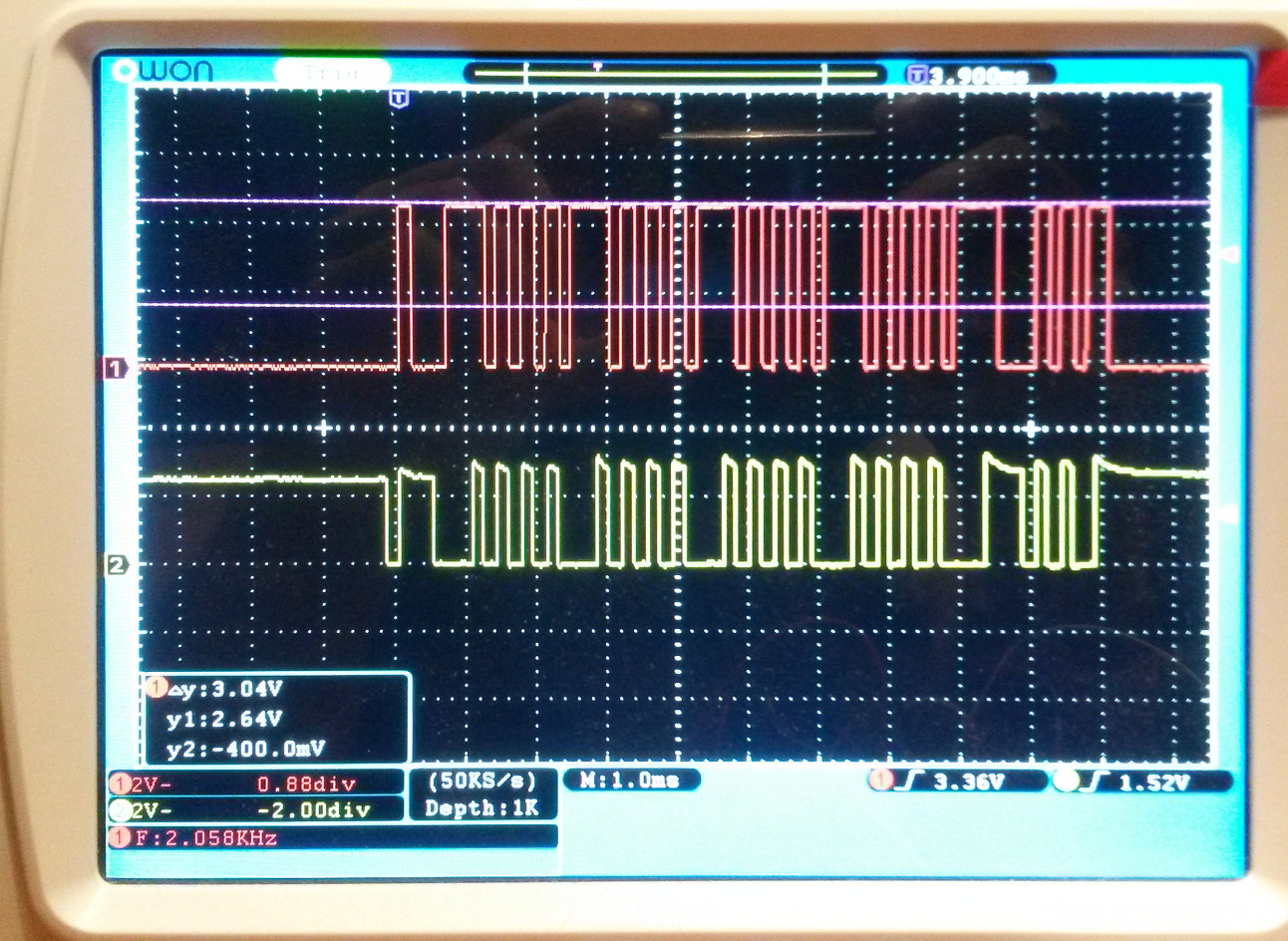
I attach a schematic and the results on the scope.
The red signal is after the transistor and goes into the arduino. (High is pretty much 5v and fine for IO. Tested OK.)
The yellow signal is the calipers data pin under load. (connected to the transistor circuit)
Disconnecting the transistor heavily changes the voltage for the caliper.
Questions:
- How do I calculate resistor values for such a setup for the divider and the emitter circuit?
- What happens when the transistor opens/closes. How does it affect the voltage/current for the caliper? The open transistor creates a second voltage divider and thereby brings the caliper down, correct? What else?
- Where do these slopes on the calipers pin come from? Without the emitter circuit the signal is "perfectly" square.
- How do I decouple the calipers voltage to keep it (almost) constant?
- What changes when I connect the second caliper output with the same emitter circuit. (I already did that and it "works". Again, I want to understand what is going on.)
(Just in case: I am not a native speaker. If something reads strange I might have messed up a technical term. )