Interfacing NO2 sensor with Arduino Mega 2560

Hey guys, I'm currently attempting to use an NO2 2 Click sensor with an Arduino Mega 2560. I'm quite new to Arduino, so I'm currently doubting my work. Any help/ pointers would be appreciated, especially regarding the connections of the sensor to the Arduino Board, as well as the code itself.

NO2 2 Click Sensor

Sensor Schematic

Chip Datasheet

Sensor Datasheet

The pins are connected as follows:
(Using an Arduino Mega 2560)

CS - 53
SCK - 52
SDO - 50

I had the PHT pin connected to PWM (pin 3), but I found it wasn't making a difference to anything, when connected or disconnected. I can't figure out exactly what purpose this PHT connection has, as there's no resources about it online. If anyone could help me understand what this pin is/ how it should interact with the Arduino that would be greatly appreciated!

My code so far is as follows:

#include <SPI.h>

// Define the SPI pins 
 int pinCS = 53; // Chip Select (CS or SS) pin
 int pinSCK = 52; // SPI Clock (SCK) pin
 int spiMISO = 50; // MISO (Master In Slave Out) pin

// Define calibration constants for the sensor
 int Offset = 0;
 int Sensitivity = 2;

void setup(void) 
{
  Serial.begin(115200);
  pinMode(pinCS, OUTPUT); // Set the CS HIGH - idle
  digitalWrite(pinCS, HIGH); // Set the CS HIGH - idle

 //start the SPI
  SPI.begin();
  SPI.setBitOrder( MSBFIRST );  
  SPI.setDataMode( SPI_MODE3 );  // Modes 0-3 - collect data on different settings
  SPI.setClockDivider( SPI_CLOCK_DIV16 );
 
}

void loop() {
  digitalWrite(pinCS, LOW);  // Select the Sensor (as it collects data when low)

  // Read data from the sensor
  // using float instead of int to be able to obtain decimal places
  float(SensorValue) = SPI.transfer(0x00); 

  digitalWrite(pinCS, HIGH);  // Deselect the Sensor
  Serial.print(SensorValue);

  // Convert the bytes to numbers
  float(SensorReading) = map(SensorValue, 0, 255, 0, 1023);  

  //adjust for the sensitivity and calibration
  float(NO2_Conc) = (SensorReading - Offset)/Sensitivity;
  
  // Display the reading in the Serial Monitor
  Serial.print("Sensor Reading: ");
  Serial.print(NO2_Conc);
  Serial.println(" ppb");

  delay(1000);  // Frequency of sample rate
}

This returns a value to me in the Serial Monitor. However, the values don't seem very organic. They read as ~48, with little variation, and then jump up to ~500 for a while, and then back down. I'm worried that this isn't measuring NO2 concentration, and is actually just returning an arbitrary value from the sensor/voltage source or something. Any help/guidance would be greatly appreciated.

Cheers
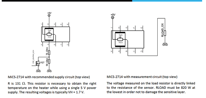
As described in the datasheet and the sensor schematic, that pin enables the heater, which is an essential feature of the sensor. The heater must be operating at the correct temperature or the readings will be meaningless.

Most sensors of this type require a burn-in period before valid readings can be made, (in some cases up to 72 hours) but the data sheet doesn't seem to mention this. Study all the available literature, and if necessary, contact the manufacturer for more information.

From the product page:

How does it work?

NO2 2 click is equipped with the MiCS-2714 sensor, a compact MOS sensor from SGX Sensortech. This sensor consists of a micromachined metal oxide semiconductor diaphragm, with an integrated heating resistor. The resistor produces heat which catalyzes the reaction, which in turn affects the electrical resistance of the oxide layer itself. The temperature of the heater is quite high: it is in the range from 350 °C to 550 °C. After the initial preheating period, the sensor can detect gas changes in time intervals below two seconds.

Brilliant thank you. I had it originally connected it up via the PWM pin (Pin 3), as I thought it was the preheating pin. On the manufacturers website it's connected via PWM. I started to doubt myself though, as I struggled to see any difference when it was connected or not. I now realise I haven't been letting it preheat for long enough.

Would it be okay to simply connect the 5V power source to the pin, as according to the data sheet there's a resistor built into the sensor which would reduce the voltage to 1.7V when it reaches the heater:

Or is there some reason for using the PWM connection which I'm missing?

Thank you kindly for the aid so far.

I don't know. Ask the manufacturer.

Unless you use the Arduino PWM function, the PWM pin is just a digital output.

No worries. I was originally using the PWM function to deliver an average pulse of 1.7V. I then changed the code, so the max voltage it delivered was 5V instead.
I will just connect it to the main 5V power supply for now and see how it goes.

Thanks for the help again, it's greatly appreciated.

Why?

It was a mistake originally. I had established that the heater needed 1.7V, I missed the fact that it had a built-in resistor to achieve this.

This topic was automatically closed 180 days after the last reply. New replies are no longer allowed.