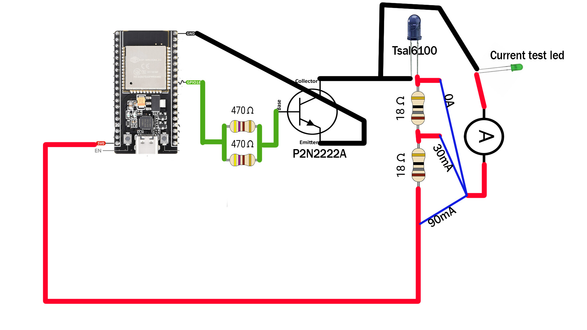
Hello, I have a small circuit I set up for a lasertag project I am working on, I am using a nodemcu32s clone as my main board, an npn P2N2222A transistor, a tsal6100 and resistors soldered in parallel and series for correct resistances but for some reason when I measure the current across the testing led I soldered on, it always seems too low, my initial target current was 100ma but even though the current is really small I somehow already managed to burn through a few ir led's. I attached the current circuit scheme below.
While you can drive TSAL at high currents (short pulses), absolute maximum continuous current is 100mA. With 36R resistor you are likely already slightly above that.
Also, is your TSAL genuine Vishay emitter?
The maximum current of this TSA6100 is 100mA.
When the transistor conducts, considering a voltage drop of 0.7V across the transistor, we will have 4.3V between the LED and the 18 Ohm resistors.
The voltage drop across the LED is 1.3V, and then across the resistors is 3V. (4.3 - 1.3) = 3
Therefore the current across the circuit is 3/(18 +18) = 0,166
Therefore the current across the circuit is 3/(18 +18) = 0,083
Or maybe half of that...
But the thing is, when I am testing it with the current testing led I get basically 0ma after the 2 resistors and 30ma if I use only one 18ohm resistor
I am not sure if my ir led's are genuine Vishay but from the shop that I ordered them from it said Tsal6100 so I would hope that the specs are somewhat the same.
If you want to test the current, measure the real resistance of your 18R+18R. Then you only need to measure the voltage across those 2 series resistors and calculate current.
There are chances, you shorted something with your amp meter setup. Just keep the essential circuit.
Double up your resistance for now. AE LEDs are not good for 100mA.
When your setup is ready and you only send tiny pulses of few ms, you can reduce the resistance.
But I still don't understand why the led only works when i either completely skip the resistors or only use one of them, when it's wired through 2 resistors it doesn't light up
Like said, measure the resistance of your 2S resistor. Is it 36ohm?
What is this test LED and why are you measuring the current through it?
It will tell you nothing about the current through the TSLA6100.
You should be measuring the current through TSLA6100.
Yes
Good, read post#7.
so would i need to divide the voltage of 4.6 by the resistance of 36ohms?
Oh, I didn't think of that thankyou. The current is 70ma

Unless you made incorrect connections with the ammeter, I don't understand how you burned a few
the setup was a bit different on that one, it was around 90ma
So exactly how do you have things connected for your actual setup that you are having problems with?
Just checked, when the gpio is low the voltage on the 2 resistors is 0 and when the gpio is high the voltage is 3.8. I think i measures something wrong the last time