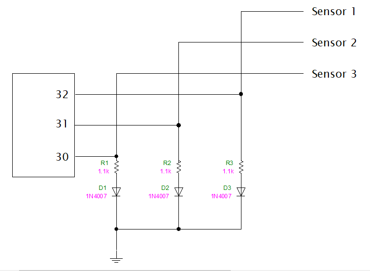
When I find something with the left IR sensor even though there is an output the Arduino pin 32 doesn't detect it.
When the middle sensor has output the Arduino pin 31 detects it. But the Serial monitor shows that both 31 and 32 have detected something. Playing with the left IR sensor still does nothing. Both are controlled by the middle one.
Right IR sensor is unaffected by them.
Instead of a breadboard I'm actually using a perforated board. The first thing I did was freshen the connections on it but nothing got fixed.
Using a multimeter I found no errors in the connections. No shorts.
#define pin1 30
#define pin2 31
#define pin3 32

void setup() {
  // put your setup code here, to run once:
  Serial.begin(115200);
  pinMode(pin1, INPUT);
  pinMode(pin2, INPUT);
  pinMode(pin3, INPUT);

  Serial.println("Starting in: ");
  Serial.println("3... ");
  delay(1000);
  Serial.println("2... ");
  delay(1000);
  Serial.println("1... ");
  delay(1000);
  Serial.println("Started!");

}

long timer;
bool st = false;
int c = 0;

void loop() {

  long timer_now = millis();

  bool s1 = digitalRead(pin1);
  bool s2 = digitalRead(pin2);
  bool s3 = digitalRead(pin3);

  if(!st) {
    st = !st;
    timer = millis();
  }
  else if(st) {
    if(timer_now - timer >= 1000) {
      Serial.println(c);
      c+=1;

      Serial.print("Sensor 30 :");
      Serial.println(!s1);
      Serial.print("Sensor 31 :");
      Serial.println(!s2);
      Serial.print("Sensor 32 :");
      Serial.println(!s3);
      Serial.println();


      st = !st;

    }
  }

}
How are you shielding the other two sensors? I can't work your code just now, so I wonder if you are sure the other two can't see the same signal.
If you are shielding them for tests, be sure the material of the shield is opaque for IR wavelengths - lotsa plastic is not.
HTH
Now looking at the code it appears you are using IR receivers that expect a modulated IR signal like a remote control, and are not meant to be simply digitally read. You would need a library to help.
So say exactly what those three things that look like transistors are.
You also have declared your pins as INPUT so if those photo diodes or transistors are not conducting, those pins are floating (not connected to HIGH or LOW) so they could read anything. You need to make them INPUT_PULLUP or add external pullup/pulldown resistors.
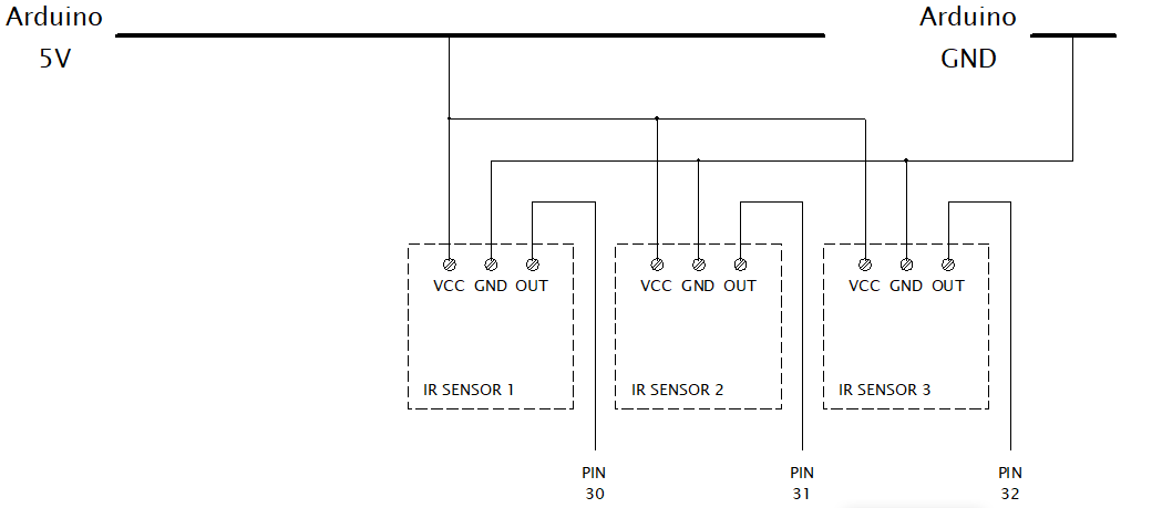
Welcome! I would expect to get what you are apparently getting. Your picture shows an Arduino UNO, not a MEGA. Different boards different pins. Also how are you powering this?
I haven't been shielding them. I thought about this being an issue but even when the Arduino is not receiving any other signal, the same thing is still happening. I have tried swapping cables and sensors, and nothing has changed.
** I forgot to mention that a few days ago I had an issue with my Arduino: It wouldn't turn on and when I checked the voltage regulator, the OUT and GND pins of the regulator were shorted.
The next day it worked just fine. Is it possible something got fried during all this and all I have to do is just use other pins?
Except you have the sensors on different pins, are using a Mega not the UNO and the sensors in your picture are totally different to the ones you are actually using.
Misleading at best. You've wasted time, ours and your own.
Where did you get the idea to add the resistor and diode to the output of the sensor? If you dreamt that up yourself, stop dreaming.
Your incomplete and misleading answers make it difficult to solve. Start from ground zero, new sensor(s) and Arduino. Remove the diodes and resistors, no idea what they are there for. Post links to technical information on each of the hardware devices. Good Luck!
Hey, I finally found the issue to be with the screw terminals that used to connect the cables to the Arduino and I'm not sure why. As soon as I removed them everything worked as expected.
I just want to apologize for the bad communication and say thank you to all of you for trying help, I really appreciate it!
The "start from zero" advice was good!