Hi guys,
So i tried this circuit to try and drive a 12volt dc motor with blinking pwm output
The LED works fine as supposed to but the motor doesnt.
Can you help me figure out why the FEt doesnt switch
Thank you

Hi guys,
So i tried this circuit to try and drive a 12volt dc motor with blinking pwm output
The LED works fine as supposed to but the motor doesnt.
Can you help me figure out why the FEt doesnt switch
Thank you
Broken MOSET? Schematic diagram looks OK for me. Try to remove R4
The IRF530 is totally unsuitable for most Arduino projects, even though it is supplied in some beginner's kits. It needs 10V on the gate to turn on fully. If you did not use the exact same optoisolator as in the posted schematic, there may not be enough gain.
Furthermore, that circuit lacks the required inductive kick diode, and could end up destroying associated circuitry.
Use a logic level MOSFET instead. The IRL530 or IRL540 would be OK, but there are many, many others.
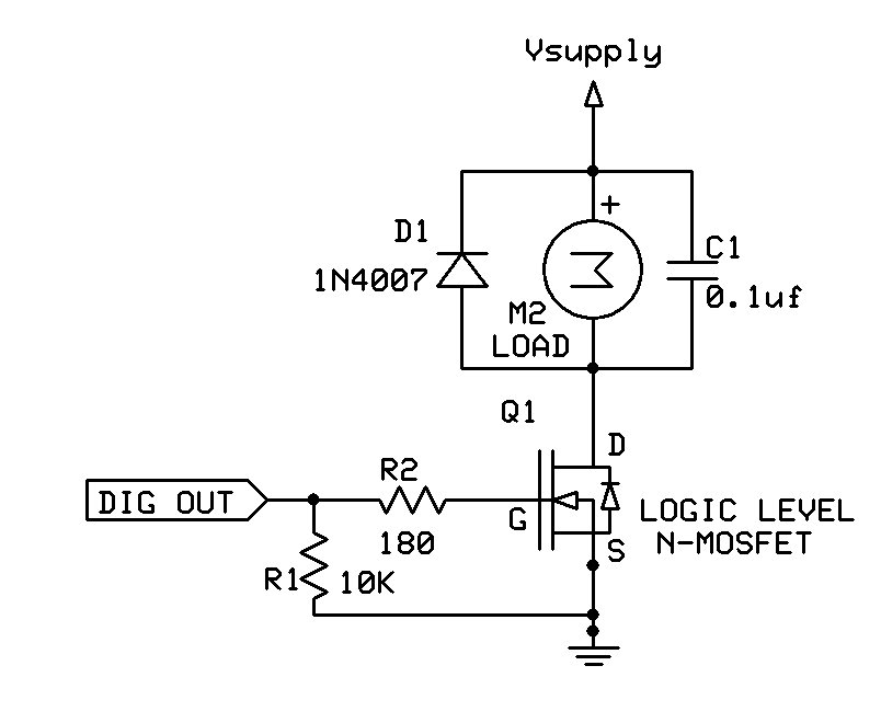
Here is a much simpler circuit (lacking optoisolation):
alesam:
Broken MOSET? Schematic diagram looks OK for me. Try to remove R4
Tried that ,still nothing
jremington:
The IRF530 is totally unsuitable for most Arduino projects, even though it is supplied in some beginner's kits. It needs 10V on the gate to turn on fully.Use a logic level MOSFET instead. The IRL530 or IRL540 would be OK, but there are many, many others.
Why is it unsuitable for arduino?
jremington:
. If you did not use the exact same optoisolator as in the posted schematic, there may not be enough gain.Furthermore, that circuit lacks the required inductive kick diode, and could end up destroying associated circuitry.
I used the exact same components in the schematic , and the motor i used has a built in diode
Why is it unsuitable for arduino?
As stated, it requires 10V on the gate to turn on.
the motor i used has a built in diode
What motor? Post a link to the product page or data sheet.
In the unlikely event that the motor does have a diode, perhaps you installed the motor backwards.
jremington:
As stated, it requires 10V on the gate to turn on.
Have you seen the a schematic from OP? It provides 12V to MOSFET gate
It provides 12V to MOSFET gate
No, because the optocoupler forms an illumination-dependent voltage divider with a 1K resistor and the LED. In order to provide 12V, the phototransistor would have to be defective, with a collector to emitter short circuit.
If the optocoupler is functional but the gain is not high enough, or the optocoupler LED resistor too high, the voltage divider won't provide the 10V necessary to switch the MOSFET to full conduction.
It is a poorly designed circuit.
Medtlili:
Hi guys,So i tried this circuit to try and drive a 12volt dc motor with blinking pwm output
The LED works fine as supposed to but the motor doesnt.
Can you help me figure out why the FEt doesnt switch
Thank you
Phototransistor based optocoupler is likely too slow for this, but the 1k resistor on the input to it
will easily starve the output of enough current - try 120 or 150 ohms. Losing the LED on the output
side will also help the MOSFET get enough drive.
Any reason not to use a MOSFET driver chip to drive a MOSFET - its what they are for and
1000 times faster than an opto coupler (no exageration).
Following the above suggestion, try this with your optoisolator. Should work with the IRF530.

It will be very slow and waste power.