Hello everyone, I wish to control three ST3025 servos and I thought of using an Arduino Uno and an Adafruit PCA9685 since I've used them in the past.
Servo specs:
ST3025 Input Voltage:** 6V-12.6V (typ. 12V)
Rated Current (each):** 1.5A
Locked-rotor Current (each):** 4.4A
I have seen conflicting data sheets and testimonies on whether I can power the PCA9685's V+ terminal with a 12V external supply (for my 12V servos). Usually 5-6V are recommended but I've also seen online reports that it can go up to 12V. I'll ensure PCA9685 VCC is powered by Arduino's 5V, and common grounding, but is this enough to make it safe and reliable? Otherwise, any solutions/alternatives? Using the (too-powerful) servos at 6V would be fine for my application but is not very advisable, right?
One other question, (and since these 3 servos are an overshoot for my application,) should I still stick to the theoretical max peak of 3×4.4A=13.2A, or can I make it lower ~8A and still be safe?
One thing it will depend on what the Vgs(max) rating is for the MOSFET on board. A recent, real Adafruit board will have an AOD417, which has a Vgs(max) rating of +/-20V. So 12V is fine.
Older Adafruit boards used an different (smaller) MOSFET. Clone boards could use anything. Check which MOSFET is on your board and then check its datasheet.
Your question actually has two answers No and No . The IC is rated at Operating power supply voltage range of 2.3 V to 5.5 V, therefore not good at 12V. The Adafruit module will allow you to you can power servos with up to 6V on the V+ line. Therefore again NO to 12V. I cannot find a higher voltage rating for you, sorry.
The screw terminal (and V+) is only connected to the power rail of the servos.
It has nothing to do (has no connection to) the PCA9685.
Doesn't matter what voltage you connect to the screw terminal.
The only limitation could be the ideal diode (mosfet) on the board, if your board has one. Some do, some don't. Then the limit could be 20volt.
The PCA9685 itself is powered via the VCC connector with 3.3volt or 5volt, depending on the logic level of the Arduino used.
Leo..
Yes and yes.
12volt on the screw terminal is safe for all versions of a PCA9685 board.
As said, it has nothing to do with the PCA chip.
Only grounds are shared, nothing else.
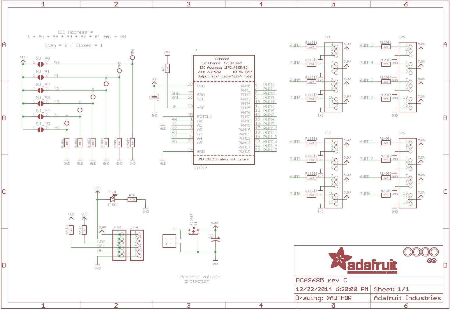
Look at this diagram.
Bottom/middle. J1 is the screw terminal, connected to the ideal diode (FET), which connects to the 5.0V rail, which only connects to all middle pins of the servo connectors, nothing else. 5.0V is a misnomer. They should have named that rail V+ or "servo power".
Leo..
Correct me if I’m wrong, but what I believe would matter is the expected signal level on the pulse input to the servo. Will a 5 or 3.3V pulse be a high enough level for that input? A data sheet for the servo should reveal that(I do NOT expect a problem, but it is good to check). Voltage level on the power pins of the servo are irrelevant, as long as the GND of the power is connected to the GND of the Arduino, for signal reference purposes.
On a different note(tangential, OP may ignore), yet another I2C board with pullups for SDA and SCL, with no way to disconnect them short of desoldering; despite the use of jumper pads on the address pulldowns. Adding those means the designers intended multiple boards to be connected. Why not make the pullups configurable, too? Such shortsightedness boggles the mind.
No, don’t supply 12V to the PCA9685 V+ pin, it’s only rated for ~6V max. You can still use 12V servos, just power them directly from a separate 12V supply (not through the PCA board). Connect only the control wires to the PCA9685, and make sure all grounds are shared.
For current: if you’re not stalling all 3 servos at once, an 8A supply might be fine, but a 12A SMPS gives you safer headroom.
This is from there manual and in a RED background on page 9:
The VCC pin is just power for the chip itself. If you want to connect servos or LEDs that use the V+ pins, you MUST connect the V+ pin as well. The V+ pin can be as high as 6V even if VCC is 3.3V (the chip is 5V safe). We suggest connecting power through the blue terminal block since it is polarity protected.
The schematic on page 27 shows the circuit.
Since they designed it, sell it, and warrant it I will go with what they stated.
Serious inspection of that posted schematic would reveal that the screw terminal + only feeds the + of the servo connections. The chip is powered from the VCC connection, which should be 5V, or possibly 3.3V.
The only risk to ‘the chip’ from a higher voltage used for the servos comes when either
a) the user shorts that + pin to the PWM pin by mistake/poor cabling, or
b) a failed servo feeds the + voltage back to ‘the chip’ via the PWM pin.
We still have no determination of the acceptable signal level for the OP’s servo.
If I read the model information correctly, that servo isn’t PWM capable, but rather “TTL” capable, whatever that means to the manufacturer. The website I was able to locate is very scant on information about the various models and communication modes for the many servos listed. Perhaps our OP could provide a link to educate us on exactly what his device’s capabilities are, because right now I’m reasonably sure he’s wasting his time and ours with the PCA9685 and that servo.
I think this is a typical example of a user, mixing up the chip PCA9685 with the breakout board sold by AdaFruit under the same name. One of my pet peeves and a trap fallen into by a lot of people giving advice here.
The point is not do not tell a poster he is wrong, tell them they are mixing up the chip and the breakout board.
This is from the same manual (page 6) and from their website.
V+ This is an optional power pin that will supply distributed power to the servos. If you are not using for servos you can leave disconnected. It is not used at all by the chip. You can also inject power from the 2-pin terminal block at the top of the board. You should provide 5-6VDC if you are using servos. If you have
to, you can go higher to 12VDC, but if you mess up and connect VCC to V+ you could damage your board!
This is a misleading statement made by Adafruit.
6volt is indeed a maximum voltage for small hobby servos, but it's in no way the maximum voltage for that board.
As stated before, the fet is the only part in that circuit, with a max gate/source voltage of 20volt.
I would say: stay below about 16volt and you should be fine.
Leo..