My goal is to run a couple sensors and charge some batteries with a solar panel during the day, and then at night switch to battery power. I've seen it is best to charge the batteries in parallel and to power the devices in series since I need the combined voltage to run the boards. I've found an instructable on how to make a series to parallel selector switch with a DPDT, but I want to do it without physically hitting the switch.
So what I would like to know is if there is a way to take input from a photodiode and have the program act like a DPDT switch based on if it is light or dark?
Any help would be appreciated as I am fairly new to arduino circuit design.
Replace the switch with a DPDT relay controlled by the Arduino. If you want to then 'hit the switch' by hand, wire a SPST on-off-on switch to two arduino inputs. On (left) would be auto, Off is manual off, On (right) is manual on. This is also known and an "HOA" (hand-off-auto) configuration.
Hi,
IF you have enough power to run the relays with the solar panels...
You might look for a "Double Pole Double Throw LATCHING relay..
Or find a DPDT "microswitch" and have a servo push it on and off. With the right mechanical arrangement (a little 'over center') or a cam, you can only power the servo when you are changing the switch..
kydra1:
My goal is to run a couple sensors and charge some batteries with a solar panel during the day, and then at night switch to battery power. I've seen it is best to charge the batteries in parallel and to power the devices in series since I need the combined voltage to run the boards.
My advice would be to stop worrying about your DPDT switch idea, take a step back and re-think the design. It does not sound right to me. What concerns me is that the whole design could be very power inefficient. What type of battery are you using and why does your sensor circuit need such a high voltage? If the panel is charging the batteries is parallel, how can that be enough voltage to run the circuit as well? I think you are asking the wrong question. I think you should be asking how to power your circuit in the best way.
Please post a schematic and links to the components you are using, including the Arduino and sensors. The sticky post at the top of the forum section will show you how to post images and links.
Hi kydra1.
The thing to realize here is that when you do this you half the voltage to charge your cells but you must then supply double the current to charge them.
If you have two 3.6v 2000mA cells in series thats 7.2v 2000mA
Those cells wired in parallel are 3.6v 4000mA.
Charging off a solar panel on series takes 2 hours (for example) charging in parallel requires a panel with double the amperage or takes twice as long. (This does not make one pannel cheaper than the other)
Not to mention that while doing all this you must run the Arduino off another power source.
Or set up your battery system to run the arduino then get a pannel able to charge the batteries while they are running the Arduino.
Have you worked out what your system needs? Eg. Volts/Amps to run.
Without that you have no idea of the battery capacity or the pannel required to charge it.
If running a system from rechargable batteries with solar charging dont forget to factor in the cost of readily available parts (cheaper) at apposed to not readily available parts (more cost).
For example a 12v 4Ah Sealed Lead Acid battery with a controller and pannel then a buck converter from 12v down to 5v would probably do what you want.
You need to allow for the battery to be able to run the whole project for three days with no sun(charging) and the pannel should be able to supply enough current to charge the battery in as little as 6 hours of sunlight to ensure continuous running.
kydra1:
I need the combined voltage to run the boards.
Look into DC-DC Boost Converters. Cheap ones can output maybe 2A but you can buy much more capacity for not greatly more money per amp.
I have cheap ones that can turn 0.9V to 5V. The output jack is a USB jack, same as an MP3/phone charger. A low power project can run on a single AAA for a while. Or, 4 'dead' batteries in series can be drained down to .9V total.....
If you have any long wire runs, use a DC-AC inverter and switching power supplies where you want DC.
The batteries I have are 3.7 v 2500mAh I have multiple but not sure how many I will need.
The arduinos are nanos, which if I recall need 5v to run.
I have multiple sensors each with their own arduino and sd card board
Adafruit Ultimate gps
Adafruit htu21d-f temperature and humidity sensor
Adafruit mma8451 3 axis accelerometer
Adafruit amg8833 thermal camera sensor
The solar panel I am using right now is ~6v 1W ~160mA
It has been awhile but I thought voltage is the same on parallel branches and had different currents.
I have tested this setup with just the sensors (no batteries) and everything ran fine.
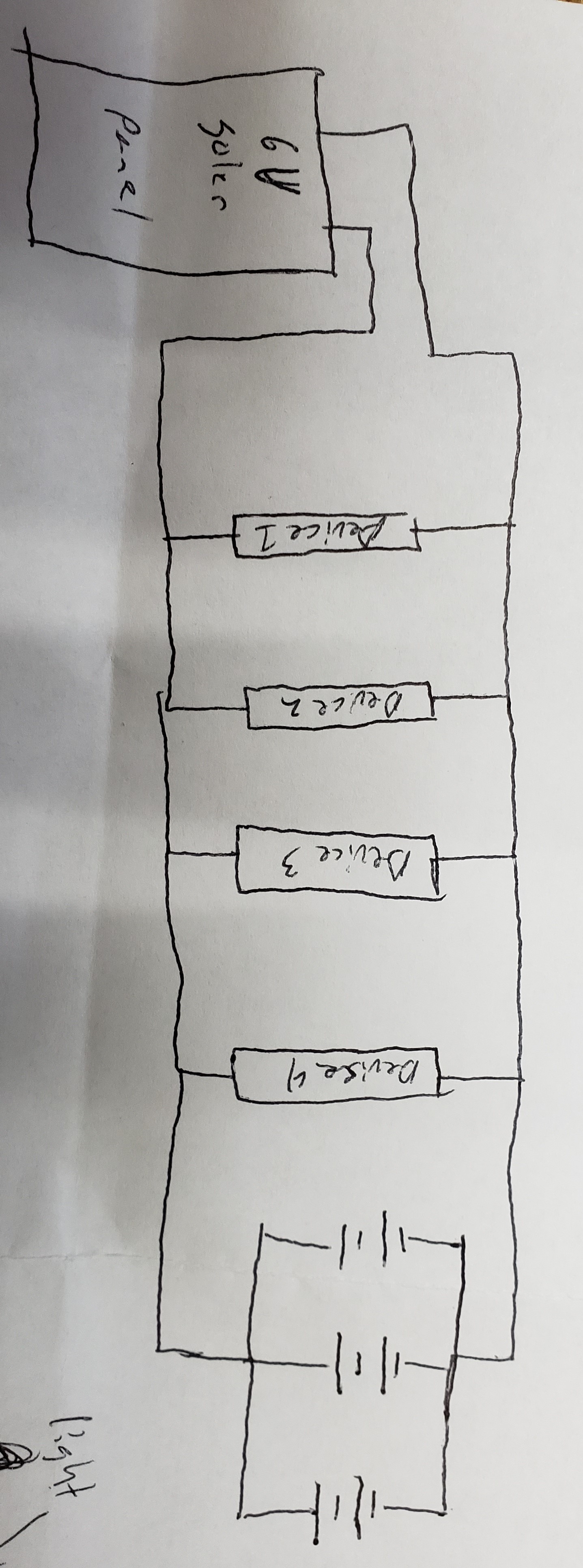
I'm not sure the best way to plan out the schematic attached is a picture of what I was thinking but not sure about it.
Nano will probably run ok at 3.7V but this cannot be guaranteed because they are 16MHz. Pro Mini 3.3V/8MHz would have been a better choice. But since you have purchased nano, try 3.7V (connected to the 5V pin not the Vin pin) and if that does not work well, look at getting a buck convertor to make 5V from 3.7V.
Yes, if you are connecting 3.7V from one or more batteries in parallel. You must not connect more than 5.5V to the 5V pin, but if you connect less than 5V there is still a good chance that it will work fine. If you connect to the Vin pin, the regulator will waste at least 0.7V, which means that there will be 3V or less for the chip and this is much less likely to work at 16MHz.
It says 600mA rated, should run 200mA (Arduino pins total max) just fine.
I bought mine at dealextreme and got a decent break on price and shipping at qty 5 or 10. It's been a while, shop around.
This is the thing that can run dead batteries (in series) run next to flat while outputting 5V.
Module Properties: BOOST
input voltage :0.9-5V
Output voltage :5.1-5 .2 V
Output Current: 600mA (single lithium input)
Efficiency: Up to 96%
Switching frequency: 500KHz
Output ripple: 30mV (MAX) 20M
Voltage indication: LED lights with a load
Operating Temperature: Industrial (-40 Celsius to +85 Celsius)
Full load temperature rise: 30 Celsius
Quiescent Current: 130uA
Load regulation: ± 1%
Voltage regulation: ± 0.5%
Dynamic response speed: 5% 200uS
Short circuit protection: No
Input Reverse Polarity Protection: No
Connection: Soldering
Input: IN + input is level, IN-type negative
Output Mode: Standard USB
Dimentions : 2.9 x 1.8 x 0.8mm (exclude USB port)
Weight: 5gr
ressure, the lower the efficiency)
Switching frequency: 400KHz
Output Ripple: 50mV (the higher the voltage, the greater the current, the greater the ripple)
Load Regulation: ~0.5%
Voltage Regulation: ~0.5%
Operating Temperature: -40 ~ +85
If your PV is between 1V and 5V, go find that thing's daddy to get you lots of 5V.
You can get converters that adjust, there's a brass screw, in boost and buck.
You want AC over long runs to avoid transmission losses. With DC you need thicker wire cables.
You know, this thing I have used in many projects that are similar to this:
I use it for raspberry pi solar projects I've done. Awesome little thing! No programming needed. You just use a DC-DC converter on your panel, set it slightly higher than the battery voltage, and the board will select whichever is highest.
You could collect solar to heat a water drum and tap off that with TEGs into the night.
There's a powerplant in the southwest US that heats oil in acres of pipes using trough reflectors. The place is supposed to run full power until about 11PM -- for a city.
2009 - GreenPowerScience heating water for house.
If it's easier to make flat slats, as long as they're no wider than the pipe along the axis it still puts all the light on the pipe.
The trough has to be lined up E-W and able to tilt up or down. When the bottom of the trough is in the shadow of the pipe it is close or right. That angle changes just over 1/4 degree per day, change 2 deg once a week is fine.
Suppose you set stovepipe in a trough and blew air not terribly fast through that? Convection oven? Save on electric/gas/wood.
kydra1:
I have multiple sensors each with their own arduino and sd card board
Adafruit Ultimate gps
Adafruit htu21d-f temperature and humidity sensor
Adafruit mma8451 3 axis accelerometer
Adafruit amg8833 thermal camera sensor
Any reason for a Nano for each sensor?
Are they in the same place?
Do you need continuous sensor readings or at intervals?
Thinking of sleep mode to keep load current down.
What is the application?
Thanks.. Tom..
Each has its own because once I had the code for the sensor reading and the write to SD the RAM was at ~73% past that I was getting stability warnings thought I had cut code down as much as I could, still new to the coding.
They are all relatively close in the same package.
Taking readings at intervals, did not know there was a way to do a sleep mode. Just having the program wait 60000 ms for example.
Building a multisensor probe that can be put out in a field or such and left alone for prolonged time. Hence the solar power and batteries.
You could dedicate a controller to the SD which can take time writing pages as the controller in the card is wear-leveling.
The ATmega1286P (costs $5 or $6 for the 40-pin DIP) has 16K RAM and 2 serial ports as well as SPI and I2C. You can put one on a breadboard or PCB and program it with the Arduino IDE. It runs the SPI and SDFat libraries, you can buffer write-to-SD data 12K or more. That takes a certain amount of log time to fill. When the SD finishes its hiccup, it can eat 512 byte pages fast until the next.
The SD is the drive and the controller be the buffer, could also provide a simpler interface than the SD library.
This is a breadboard Arduino page that shows the Uno chip 328P and "The Mighty" 1284P.
The software works for the same chips on boards but those usually come bootloaded. With this you can bootload many AVRs.