I copied from google a circuit for effective switch debouncing using 74HC14. Is my design have any problem ? I have doubts about position and value of resistor of because I will power up with 3.3v and want to use red led.

1 Like
That should work, but R2 could be a lot higher. 1K should result in bright light with modern, efficient LEDs.
C1 could be 2.2 uF and still give reasonable debounce timing.
Why not debounce in software using easybutton?
That is a great circuit. I have used it for more years then I want to remember. I am not sure what LED you are using but it appears you are pushing about 24mA through it. The output capacity of the 74HC14 is about 25mA. If you have several of these you will be drawing more then the 74HC14 can supply if they are all on and it will get hot. Consider something in the 200 to 500 Ohm range for R2. You can use a lot smaller resistor, I generally used 0.1 for C1 and 100K for R3. I suggest you change R1 to something in the 3K range as you want to keep 1mA or greater going through the switch to keep it from oxidizing the contacts.
That small a value for R2 will light up the room. Way too bright. I use 2K or 3K for my LED indicators.
But there are a dozen button libraries that do the same thing in software.
I was just recently looking for debouncing ICs, there are, starting with a single button debouncer to like 8 in the same chip. I suggest you look it up as well
With the time constant ~1.0s made with R1,R3,C1, it will be extremely sluggish. What on earth are you using it for?
Software debounce is one of the simplest functions that exist in MCU code. You should use it instead, unless you have a really solid reason for this circuit.
Even with no library, a few lines of code will do it.
If you make R3 around 33R, the the switch wetting current will be ~100mA. This wetting current will clean the contacts and is likely to make the switch last a long time. 33u will be a physically large cap, consider a small ceramic, say 100nF. Smaller and lower cost.
As others have said R2 is very generous on the current from HC14 and through the LED.
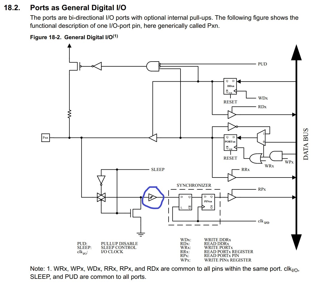
The buffer and LED are completely unnecessary. The LED isn't even part of the the input smoothing circuit, it's just an extraneous indicator. The chip's IO ports already have Schmitt trigger input buffers integrated into them (circled in photo), so the 74HC14 is redundent.
If you properly code your program, switch bounce can easily be filtered out in software. If you insist on doing it in hardware, turning on INPUT_PULLUP with a capacitor in parallel with the switch is all you really need.
Thank you for all suggestions. This circuit will be used for water meter pulse readings on MRK board with with interrupt. Initially I tried debouncing with software but results didnt satisfied me becuase reed swicth on water meter works with magnets and I think it sometimes creating multiple pulses or noise on pin. My beliveing this kind of filtering will supply more reliable results.
would be good to scan it with a scope and see what noise you are dealing with, then mitigate exactly
its a worthwhile investment if you deal with electronics more then once a year, you will thank yourself every time u use it for the rest of your life, even cheap ones go a long way XD.
That is precisely what debouncing is designed to eliminate. So it's likely you only need to increase the debounce lockout interval.
This topic was automatically closed 180 days after the last reply. New replies are no longer allowed.