What's that device, up to the right in the picture, showing a yellow arrow?
Do not apply 5 volt to the UNO 5 volt pin when USB is connected.
Do not run motor current through a breadboard.
What's that device, up to the right in the picture, showing a yellow arrow?
Do not apply 5 volt to the UNO 5 volt pin when USB is connected.
Do not run motor current through a breadboard.
Breadboards are for temporary experiments with low power logic circuits and cannot be used for motor currents.
Solder motor and power wires to the motor driver, or use screw terminals if present.
Be sure to set the current limit correctly and use an adequate motor power supply (8 to 24V, 2 Amperes).
Duplicate of Is my setup rights for a NEMA 17 - #17 by jremington ?
I suspect that in the earlier thread, @joe123846 didn't get the desired answer.
it now allows me to download code. Is this a problem or is it fine.
the motor worked fine at 5v but then stopped working after now im using new components and it still wont work well. I put 12v into the power module i have got then it makes it 5v and then the motor used to work fine but now im trying to get it to work again.
According to the manufacturer's data sheet, the A4988 motor driver requires a motor power supply of 8V, minimum.
the motor worked fine at 5v but then stopped working
That is a strong hint that you are doing something wrong. Forum members have pointed out of a few of those mistakes. Fix those and if you are still having problems, come back.
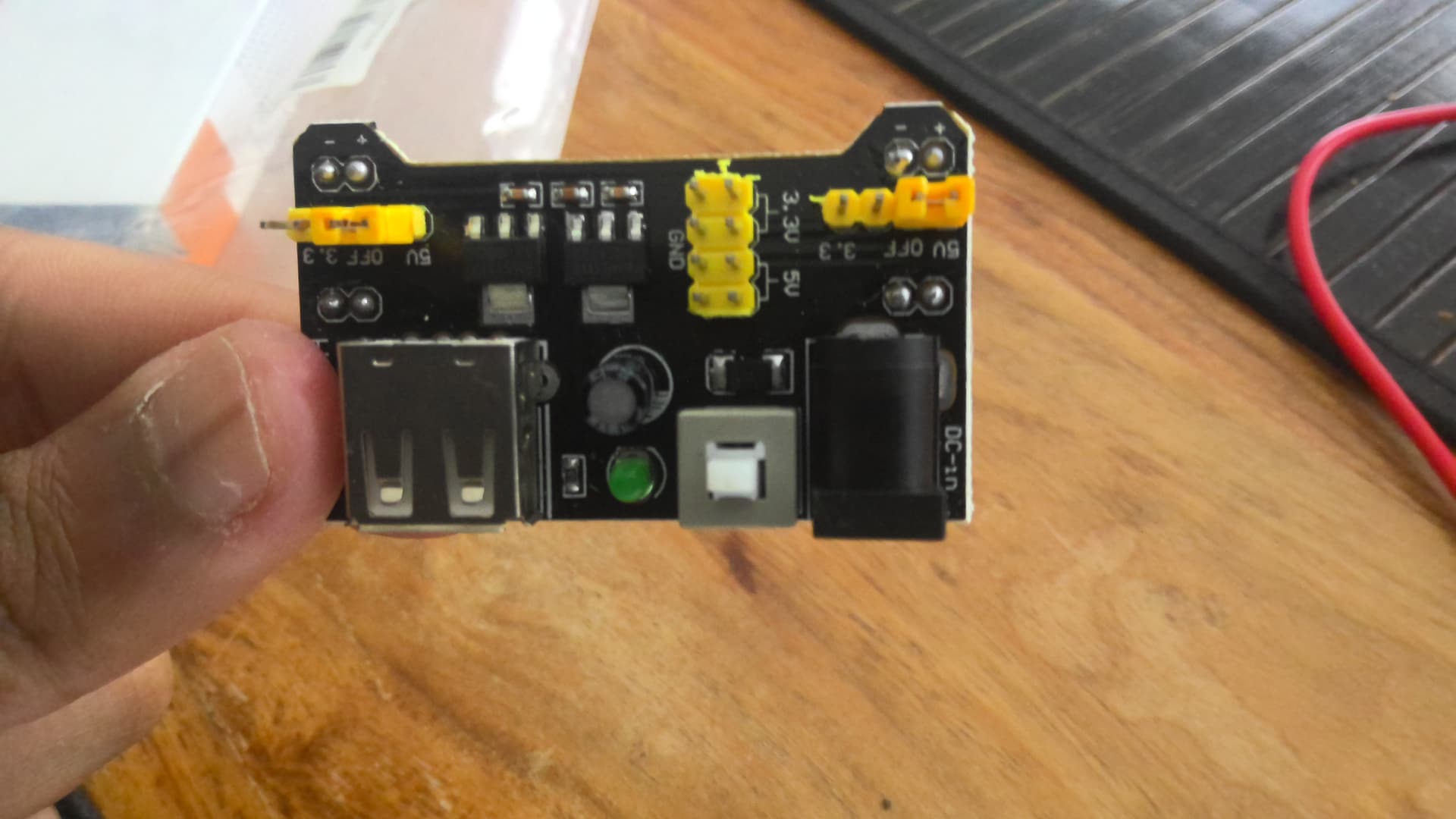
if it is necessary to solder than can anyone send a link to a small compact power supply. since i only have a driver, wires, arduino and a power supply compatable with breadboard shown below. I connect this to a 12v plug.
this is my motor
That module is useless for motor control of any kind !
The regulator will blow as it is not rated for many amps.
Am surprised it still works.
You probably burned out the A4988.
From the Pololu website:
Warning: This carrier board uses low-ESR ceramic capacitors, which makes it susceptible to destructive LC voltage spikes, especially when using power leads longer than a few inches. Under the right conditions, these spikes can exceed the 35V maximum voltage rating for the A4988 and permanently damage the board, even when the motor supply voltage is as low as 12V. One way to protect the driver from such spikes is to put a large (at least 47uF) electrolytic capacitor across motor power (VMOT) and ground somewhere close to the board.
Warning: Connecting or disconnecting a stepper motor while the driver is powered can destroy the driver. (More generally, rewiring anything while it is powered is asking for trouble.)
Also, like @jremington said Don' use breadboards for the motor connections!
do you know any small and compact power modules that can handle the current. Couldnt find any.
The A4988 motor driver won't work well or at all with that high impedance motor.
Since the motor is classed as "unipolar", you need to wire it in a non-standard way with a bipolar motor driver, or use a unipolar stepper motor driver.
the driver in the diagram is for unipolar and is using the A4988
And you are posting here because it is not working, right?
Good luck with your project!
yes. do you know any good compact power modules since i need one better than the one i sent
i dont know any small modules that could handle the current needed for my motor
should i send a picture of the motor etc when it was working with the breadboard and power module. Its not a wiring diagram but a physical photo.
I use these types of supply on my CNC's
Get one that has plenty of amps.
Normally I would get the 10 amps or higher depending on the project.