Fine, but you can't connect it directly you need some sort of amplifier.
1 Like
You think that the resistor and capacitor suggested is not enough?
I think that this basic audio amplifier would be great for my project:

I'm going to try to add it to my schematic. Thanks for the suggestion ![]()
Yes, you don't need any voltage gain, so go without the capacitor. But you do need current gain, so keep the volume control to stop the sound waveform distorting, by trying to drive the speaker to a higher voltage than the supply. That will cause what is called clipping and will cause a lot of distortion.
1 Like
Indeed, I didn't expect that to have much gain which is why I also mentioned amplification. There are some circuit designs that use a single transistor (2N2222, BC337 or whatever) but even this would struggle because of the impedance difference. The LM386 approach with volume control is a much better way forward.
1 Like
Thanks to both of you that insisted in the use of amplification. I though that it would be difficult but it was easier than I expected. Here's an update of my schematic:
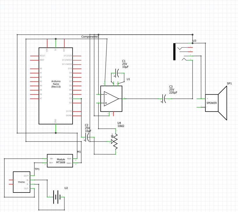
Te 250uf capacitor that protects from dc can be 220uf or 330uf? I can't find one with 250uf.
I think that low esr capacitors would be a good choise to reduce noise and have a clearer audio output. What do you think?
Grumpy_Mike, I think that the 0.05uf is the one that you suggested to remove. Am I right?
You are missing the ground from the speaker, or at least that is what the diagram looks like. You also have the volume control wired up wrong. The wiper of the pot (middle connection) should go to the input of the LM386, with the signal going into the top connector of the pot and the ground going to the bottom end of the pot. Note if these two are reversed the the volume control will work backwards. In other words anticlockwise rotation will increase the volume.
This value is not critical and basically the bigger the better, because it increases the low frequency response.
No it will not make any difference.
No, it was the capacitor that sets the gain, the 10uF on pins 1 & 6, you need the 0.05uF and 10Ω resistor to stabilise the output.
The thing about data sheets is that many times they do not use real obtainable values. So the closest you will get is perhaps 0.047uF or 47nF ( they are the same thing) the important thing is that it must be a ceramic capacitor, other types will not do.
Thanks again, I think that I finished the schematic:
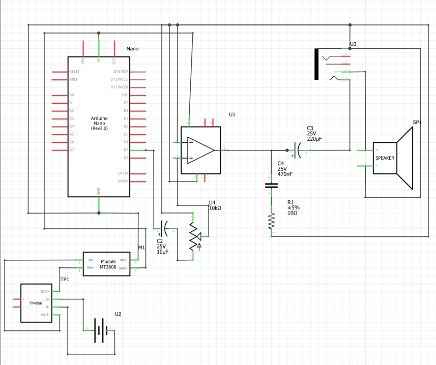
Now is time to finish the entire project schematic and pack it in a gameboy pocket shell after I tested everything in a breadboard, just a funny project to learn how open-source hardware works for christmas.
Ok a lot better. However, I made a simple error in the previous post (now corrected) that the capacitor on the output of the amplifier should be 47nF not 470nF
Perfect, thanks for clarifying that.
For future reference the standard for schematics is that the gnd is at the bottom (unless there are negative voltages present)
The LM386 wont give you much volume;
from the data sheet you can expect 3V pk-pk which is 1V rms into 8 ohms is 16mW of power.
If you want more output you can use a bridge tied load amplifier like this
1 Like
For future reference the standard for schematics is that the gnd is at the bottom (unless there are negative voltages present)
Thanks, I'll do that for my future projects schematics.
The lm4862 amplifier seems interesting and easy to implement. The thing that I'm not sure is the power consumption, the article says:
Total current consumption of the chip can be expected to be around ranges 5 mA in the absence of a music input, and to around 250 mA when it is operated at its maximum volume limit.
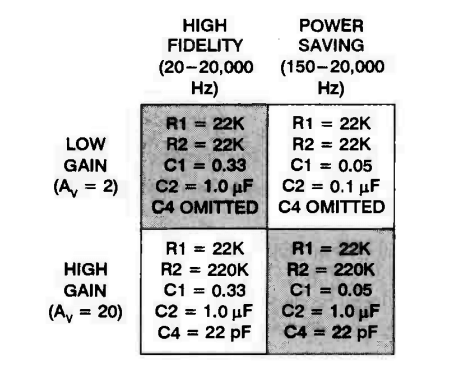
I imagine that It draws 250mA with the high gain, if I use the low gain and high fidelity configuration like the beneath picture. How much power will it draw?
This topic was automatically closed 180 days after the last reply. New replies are no longer allowed.