Hi, Hope you are all doing well.
So I'm more like an amateur here and I've this modified sine/square inverter project using an Atmega328p generating phase corrected PWM using Timer, driving a push-pull transformer through a MOSFET bridge. Everything works fine as expected and getting the desired output and waveforms. In my program, I've even added a functionality to change the duty cycle at any moment between 0-45% (Ensuring enough dead time to avoid cross-conduction)
I'm a bit confused in implementing a closed loop feedback system to regulate the output voltage. ![]() I'm planning to use an isolated voltage divider to get a fraction of the transformer output to the micro-controller ADC.
I'm planning to use an isolated voltage divider to get a fraction of the transformer output to the micro-controller ADC.
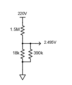
Here's the schematic of the feedback section I intend to use.

This should bring the high voltage to ADC compatible voltage level and fed to the Atmega328.
Lets say I'm setting the feedback to give 2.5v @ 220V and in my program I update the duty cycle based on this, theoretically it should work right ?
Also I'm noticing that the feedback response is not linear with an opto-coupler.
int main()
{
    while(1)
    {
        //Get the adc value from feedback
        adcVal = getADCVal();
        //Inverting since the feedback circuit is inversely proportional
        adcVal = map(adcVal, 0, 1023, 1023, 0);

        //If fb value greater than 2.5v, reduce duty cycle
        if(adcVal > 512 && dutyCycle > 0.0)
            dutyCycle -=0.01;
        //Else if fb value less than 2.5v increate duty cycle
        else if(adcVal < 512 && dutyCycle < 0.45)
            dutyCycle +=0.01;
    }
}
Looking for more like a discussion thread to point out the flaws or anything I missed. Any suggestions or insights on your previous similar projects would be really appreciated.
Thanks.