Issue uploading program onto a Pro Mini using an FTDI

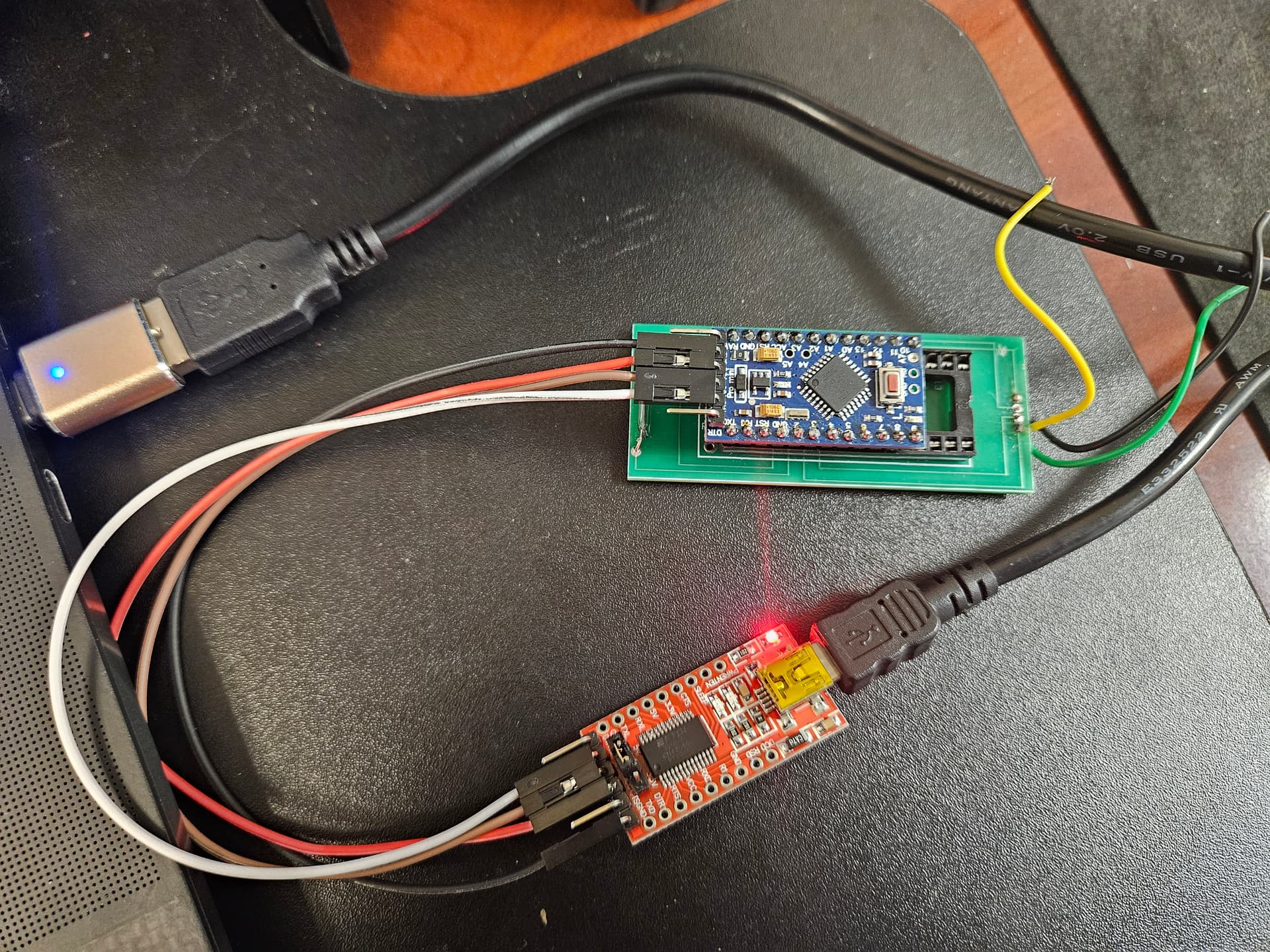
HI, I am using an FTDI USB to TTL Converter to program an Arduino Pro Mini with an UpTime Counter code for a 1602 BLUE LCD 16x2 HD44780 with IIC I2C Serial Interface Adapter Module Display.

#include <Wire.h>
//#include <WireIMXRT.h>
//#include <WireKinetis.h>
#include <hd44780.h>
#include <hd44780ioClass/hd44780_I2Cexp.h>

#define SDA A4//DIO
#define SCL A5//CLK

//hd44780_I2Cexp display(SCL,SDA);// instead of TM1637Display
/*-----( Declare Constants )-----*/
/*-----( Declare objects )-----*/
// set the LCD address to 0x3F for PCF8574AT with A0,A1,A0 address line open, default setting.
// Set the pins on the I2C chip used for LCD connections:
//                   (addr, en,rw,rs,d4,d5,d6,d7,bl,blpol)
hd44780_I2Cexp lcd(0x3F);// declare lcd object: auto locate & auto config expander chip
const int LCD_COLS = 16;
const int LCD_ROWS = 2; //(2,1, 0, 4, 5, 6, 7, 3, POSITIVE);  // Set the LCD I2C address; we many end up changing it to 2, 3, 4, 5, 6, 7 instead
// im unsure if this address is for the 8-bit or the 4 bit; we need the 4 bit
// we may also asign the address as lcd(0x3F, 16,2); sets the LCD address to Ox3F as well( programmingboss)

const int REED_PIN = 2;

int is_timing=0; // // 1 means we are timing the interval between triggers; 0 means we are not
unsigned long start_time;   // stores the start of the timing interval

void setup() { 
  // put your setup code here, to run once: sets up pin read mode and LCD display
 
Serial.begin(9600);  // Used to type in characters
pinMode(REED_PIN, INPUT_PULLUP);
lcd.begin(16,2); // initialize the lcd for 16 chars 2 lines, turn on backlight
lcd.backlight();// keep backlight on?
//----characters for display----
 //The positions on the screen are indexed starting with (0,0) in the top-left position. 
  //The first argument of setCursor() specifies which column number, and the second specifies which row number. 
  //By default, the starting location is (0,0).lcd.setCursor(6,0);// sets cursor on character 6, line 0
//lcd.print(millis()/1000);// unsure if I need for settign up count up
//delay();// figure out the time max; no longer need

lcd.setCursor(4,1);// moves LCD cursor to character 4, line 1
lcd.print("MOTE SHARK TIMER");//prints that phrase on screen
// originally I had "FREE SHARK " in () but I learned
// that there is no max time a shark can be on the line
// it is more as if the longer the shark is on the line, the more stressed it is likely to be

// ------- Quick 3 blinks of backlight  ------------- no longer needed since no max time shark can be on line
//for(int i = 0; i< 3; i++)
//lcd.backlight();
//delay(250);
//lcd.noBacklight();
//delay(250);

//lcd.setBrightness(0x0f);// may not be needed since we have a potentiometer on the back of the display
lcd.clear();

int is_timing = 0;  

}

void loop() {
  // put your main code here, to run repeatedly:
  int proximity = digitalRead(REED_PIN); // when sensor is close to the trigger

  // if (proximity == HIGH) {
    // the magnet is far from the reed switch
    
    if (is_timing == 0) {
      // trigger the start of the timing interval
      is_timing = 1;            // we are now timing the interval
      start_time = millis();   // record the current time as the start of the interval      
    } else {
      // update the LED display      
      unsigned long elapsed_time = millis() - start_time;
      int seconds = elapsed_time / 1000;
      int hours = seconds / 3600;
      int minutes = (seconds - hours * 3600) / 60;
      
      // print uptime in HH:MM:SS format

	if(hours > 99)
		hours %= 100; // limit hr to 0-99

	// Print class does not support fixed width formatting
	// so insert a zero if number smaller than 10
		
//	if(hours < 10)
	//	outdev.write('0');
	//outdev.print((int)hours);
	//outdev.write(':');
//	if(minutes < 10)
//		outdev.write('0');
//	outdev.print((int)minutes);
//	outdev.write(':');
//	if(seconds < 10)
//		outdev.write('0');
//	outdev.print((int)seconds);
}

      //lcd.print(minutes, 0b01000000, true, 2, 2);       
      //lcd.print(hours, 0b01000000, true, 2, 0);
    //}
  // } else {
    // the magnet is close to the reed switch
  if (is_timing == 1) {
      // triggers the end of the timing interval
      is_timing = 0;
      lcd.clear();
    } else {
      // we are not currently timing, so just chill
      lcd.clear();
    }

I have two issues to address:

  1. The code will not upload. The error message that appears is below.
Sketch uses 7060 bytes (22%) of program storage space. Maximum is 30720 bytes.
Global variables use 510 bytes (24%) of dynamic memory, leaving 1538 bytes for local variables. Maximum is 2048 bytes.
avrdude: stk500_recv(): programmer is not responding
avrdude: stk500_getsync() attempt 1 of 10: not in sync: resp=0x1b
avrdude: stk500_recv(): programmer is not responding
avrdude: stk500_getsync() attempt 2 of 10: not in sync: resp=0x1b
avrdude: stk500_recv(): programmer is not responding
avrdude: stk500_getsync() attempt 3 of 10: not in sync: resp=0x1b
avrdude: stk500_recv(): programmer is not responding
avrdude: stk500_getsync() attempt 4 of 10: not in sync: resp=0x1b
avrdude: stk500_recv(): programmer is not responding
avrdude: stk500_getsync() attempt 5 of 10: not in sync: resp=0x1b
avrdude: stk500_recv(): programmer is not responding
avrdude: stk500_getsync() attempt 6 of 10: not in sync: resp=0x1b
avrdude: stk500_recv(): programmer is not responding
avrdude: stk500_getsync() attempt 7 of 10: not in sync: resp=0x1b
avrdude: stk500_recv(): programmer is not responding
avrdude: stk500_getsync() attempt 8 of 10: not in sync: resp=0x1b
avrdude: stk500_recv(): programmer is not responding
avrdude: stk500_getsync() attempt 9 of 10: not in sync: resp=0x1b
avrdude: stk500_recv(): programmer is not responding
avrdude: stk500_getsync() attempt 10 of 10: not in sync: resp=0x1b
Failed uploading: uploading error: exit status 1

I have searched through this forum community for solutions and have already tried burning the bootloader and confirming the correct port, board, processor, and programmer addresses. I have also tried updating Arduino and my computer, as well as changing Pro Minis. I have three Pro Minis in my possession and the code only downloads on one of them. How can I get it to upload on the other Pro Minis?

  1. The code does not do as expected. The display powers on, but there is no data output on the screen. I want a count-up timer to display on the LCD screen, in HH:MM:SS, when a magnet is not in proximity of the reed switch in the circuit. I also want the words "MOTE SHARK TIMER" to display on the screen when the display is powered on. Below is a picture of the schematic.

The LCD Display --> ProMini
GRD-->GRD
VCC--> RAW
SDA--> A4
SCL--> A5

A 9V battery is the power source. It is connected to the GRD and RAW of the Pro Mini. The REED Switch connects to the Pro Mini via GRD and D2.

What changes to the code could I make? How would I identify the SDA and SCL pins differently?

You didn't show it in your picture. Please tell us exactly how the FTDI converter is connected to the Pro Mini.

I'm confused. If you can't upload, how can you have code running?

Have you tried to upload without anything else connected (only FTDI that also provides the power)?

Note that normal PP3 batteries have a very limited capacity; your battery might be koind-of-empty.

If one of your 3 prominis downloads fine and the other 2 not, I suspect the other 2 have either no bootloader, or another version of a bootloader on them.

You mentioned you attempted to burn the bootloader. Please know that burning a bootloader requires another (ISP) programmer and other connections to the promini you want to burn the bootloader onto. It is not possible to do that via the FTDI programmer.

image

you can turn your working promini into a ISP programmer, that in it's turn could burn the bootloader onto your two not working promini's.

Chances are that you need to manually reset the pro-mini just before upload starts. Try holding the reset button down until the IDE says 'Done Compiling' and then release it.

I used an Arduino UNO to burn the bootloader. I loaded the ArduinoISP sketch onto the Uno, then used the Uno to burn the bootloader onto the Pro Mini.

My apologies.

FTDI --> Pro Mini
GRD--> GRD
VCC--> VCC
RX--> TXO
TX--> RXI

The code only uploads onto one of the 3 Pro Minis in my possession. Yes, I only use the FTDI to upload the program. I don't think the battery is empty because it powers the display. The issue is that the count-up timer and text I put in my code do not show on the screen.

Your missing a wire, probably the one between DTR of the FTDI adapter and reset of the Pro Mini. Either manual reset the board (at the right time) as indicated by @Deva_Rishi or add that wire.

See https://learn.sparkfun.com/tutorials/using-the-arduino-pro-mini-33v/all (ignore the fact that it's about the 3.3V version).

Or e.g.
image

I just tried adding the missing connection like you suggested. I got the following error message:

Sketch uses 7060 bytes (22%) of program storage space. Maximum is 30720 bytes.
Global variables use 510 bytes (24%) of dynamic memory, leaving 1538 bytes for local variables. Maximum is 2048 bytes.
avrdude: stk500_recv(): programmer is not responding
avrdude: stk500_getsync() attempt 1 of 10: not in sync: resp=0xb9
avrdude: stk500_recv(): programmer is not responding
avrdude: stk500_getsync() attempt 2 of 10: not in sync: resp=0xb9
avrdude: stk500_recv(): programmer is not responding
avrdude: stk500_getsync() attempt 3 of 10: not in sync: resp=0xb9
avrdude: stk500_recv(): programmer is not responding
avrdude: stk500_getsync() attempt 4 of 10: not in sync: resp=0xb9
avrdude: stk500_recv(): programmer is not responding
avrdude: stk500_getsync() attempt 5 of 10: not in sync: resp=0xb9
avrdude: stk500_recv(): programmer is not responding
avrdude: stk500_getsync() attempt 6 of 10: not in sync: resp=0xb9
avrdude: stk500_recv(): programmer is not responding
avrdude: stk500_getsync() attempt 7 of 10: not in sync: resp=0xb9
avrdude: stk500_recv(): programmer is not responding
avrdude: stk500_getsync() attempt 8 of 10: not in sync: resp=0xb9
avrdude: stk500_recv(): programmer is not responding
avrdude: stk500_getsync() attempt 9 of 10: not in sync: resp=0xb9
avrdude: stk500_recv(): programmer is not responding
avrdude: stk500_getsync() attempt 10 of 10: not in sync: resp=0xb9
Failed uploading: uploading error: exit status 1

What else could I do?

successfully ?

In that case i would suggest you use the UNO also to try and upload the sketch (i always do that)
load blink onto the UNO (or a blank sketch, but blink shows you that there is something going on)
connect
tx -> tx
rx -> rx
Vcc -> 5v (assuming you have 5v pro-mini)
GND -> GND
RST -> RST

I uploaded the bootloader successfully. I believe I discovered the problem. I used the ArduinoISP bootloader, so I believe my Pro Mini thinks it is an Uno. When I changed the board in IDE from Pro Mini to UNo, the code uploaded successfully. I believe that could be why the display does not show the code even though the Arduino is programmed.

That is possible, though the differences are not that big. There is another possibility which occurs quite often. Have you set the contrast of the LCD with a variable resistor ?

That is a sketch, after you have uploaded that to the UNO, you switch boards in the IDE and then hit burn bootloader.

I haven't looked at your code since first the upload issue should be dealt with.

The I2C comes with a potentiometer. Would that do?

I did switch the board to Pro/Pro Mini and hit burn bootloader initially. When I did that, the bootloader downloaded successfully. However, the program would not upload. So, I switched the board from Pro Mini to UNo and hit upload again. The upload was successful. The code just does not display.

That is the same, yes. Have you tried adjusting it using a small screwdriver ?

which may mean that you did not upload the correct bootloader, but as said, they are almost the same, you will not have access to the extra analog pins on the pro-mini, but i think it saves some flash space. I am no expert, i rarely burn bootloaders and my pro-minis always work out of the box.

Looking at your code i see that what is left in between the comments is

#include <Wire.h>
#include <hd44780.h>
#include <hd44780ioClass/hd44780_I2Cexp.h>

#define SDA A4//DIO
#define SCL A5//CLK


hd44780_I2Cexp lcd(0x3F);
const int LCD_COLS = 16;
const int LCD_ROWS = 2; 

const int REED_PIN = 2;

int is_timing=0; // // 1 means we are timing the interval between triggers; 0 means we are not
unsigned long start_time;   // stores the start of the timing interval

void setup() { 
 
Serial.begin(9600);  // Used to type in characters
pinMode(REED_PIN, INPUT_PULLUP);
lcd.begin(16,2); // initialize the lcd for 16 chars 2 lines, turn on backlight
lcd.backlight();// keep backlight on?
lcd.setCursor(4,1);// moves LCD cursor to character 4, line 1
lcd.print("MOTE SHARK TIMER");//prints that phrase on screen
lcd.clear();
int is_timing = 0;  
}

void loop() {
  int proximity = digitalRead(REED_PIN); // when sensor is close to the trigger    
    if (is_timing == 0) {
          is_timing = 1;            // we are now timing the interval
      start_time = millis();   // record the current time as the start of the interval      
    } else {      
      unsigned long elapsed_time = millis() - start_time;
      int seconds = elapsed_time / 1000;
      int hours = seconds / 3600;
      int minutes = (seconds - hours * 3600) / 60;
	if(hours > 99)
		hours %= 100; // limit hr to 0-99
}
  if (is_timing == 1) {      
      is_timing = 0;
      lcd.clear();
    } else {
      lcd.clear();
    }

Now that does not actually compile i think, simply because the braces don't add up (1 closing brace is missing)
But more to the point, it prints something to the LCD and then clears is straight away after which nothing is printed anymore, so how about just adding a delay of a few seconds to make sure it is working first.

void setup() { 
 
Serial.begin(9600);  // Used to type in characters
pinMode(REED_PIN, INPUT_PULLUP);
lcd.begin(16,2); // initialize the lcd for 16 chars 2 lines, turn on backlight
lcd.backlight();// keep backlight on?
lcd.setCursor(4,1);// moves LCD cursor to character 4, line 1
lcd.print("MOTE SHARK TIMER");//prints that phrase on screen
delay(5000); // add 5 seconds or more if you want time to adjust the contrast
lcd.clear();
int is_timing = 0;  
}

This topic was automatically closed 180 days after the last reply. New replies are no longer allowed.