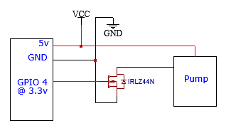
Hi, this is my first time using mosfets and want to use it as a switch to switch a 5v pump from a esp32 super mini c3. I've tried like every combination and the mosfet always gives 5ish volts or nothing except the one time I wired it High Side instead of low side in which it only would output the same voltage input into the gate. This is what my wiring is which I think matches what I found on google but still nothing.
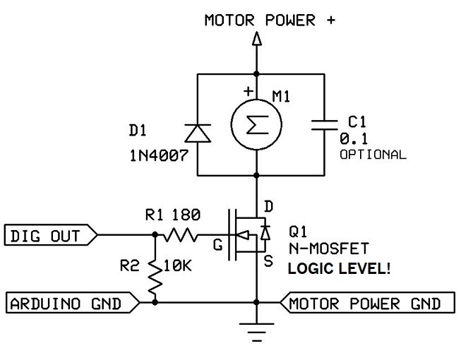
The pump motor will destroy the MOSFET with high voltage spikes, unless you use a kickback diode, as show below (D1).
Also, you should NEVER use the Arduino 5V output to power pumps, servos or solenoids, as that may damage the Arduino or even the host computer, if connected via USB.
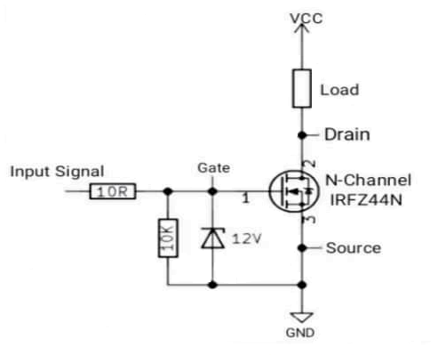
I will take a SWAG as it appears the part you have is not the part you think you have. Looking at your link and what info I could find the part will be marginal on a 3V3 system. Read the comments the first one when I looked stated you needed about 5V to get it to work. @jremington is the best solution. @LarryD will also work but you need to make the suggested changes. @UKHeliBob is a common way to connect them but I do not like it as the resistors become a voltage divider although it generally works.
A much better answer could be obtained if we knew the pump parameters and what the power supply is rated at. Connecting to the Arduino is a No-No.
Thanks for the replies, I fixed it with a 10k resistor between gate and GND, so thank you UKHeliBob, I seem to be able to power the pump fine now and the esp32 works fine, the pump is kinda weak and works from 5-12v at like 100ma and the esp32 is rated to handle up to 6v but in my experience (cranking up the bench power supply till it dies) can handle like 7v. Is the kickback diode necessary? I really don't want to wait for shipping again.
Only if you want the transistor to be able to switch on a second time.
To be fair, the first kickback may not kill the transistor. It might survive several kickbacks. But it might not. And it will die. And that could happen the first time you switch it off.