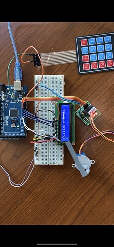
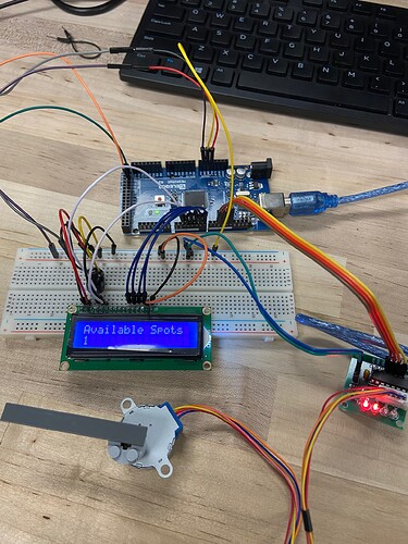
Issue with keypad and LCD

We are engineering students using an Arduino mega2560 that came with the complete starter kit for a class project. We are creating a prototype for an automated parking system using a keypad to act as a pressure plate so that when a button is pressed, our stepper motor will open a gate, and the value on the LCD displaying the number of spots available will go down. We are having an issue with our LCD where it goes completely white after a second of the code running. The counter seems to be working in the serial monitor, but the LCD is not. The LCD works properly when we remove the keypad from the code and displays the proper decreasing values. Any help would be very much appreciated!

Here's the code:

  #include <Keypad.h>
  #include <Stepper.h>
  #include <LiquidCrystal.h>

  // initialize the library with the numbers of the interface pins
  const byte ROWS = 4; //four rows
  const byte COLS = 4; //four columns
  const char keys[ROWS][COLS] = {
  {'1','2','3','A'},
  {'4','5','6','B'},
  {'7','8','9','C'},
  {'*','0','#','D'}
 }; //connect to the row pinouts of the keypad , switched pins 8 and 5 to have the pins on the arduino closer together as they are the only ones connected for testing with the button '1' in row 1, col 1.
  byte colPins[COLS] = {8, 4, 3, 2 }; //connect to the column pinouts of the keypad
  byte rowPins[ROWS] = {9, 5, 7, 6}; //connect to the row pinouts of the keypad , switched pins 8 and 5 to have the pins on the arduino closer together

  Keypad keypad = Keypad( makeKeymap(keys), rowPins, colPins, ROWS, COLS );

  const int stepsPerRevolution = 500;  // steps per revolution of the motor
  // initialize the stepper library on pins 8 through 11

  Stepper myStepper(stepsPerRevolution, 10, 12, 11, 13);// did this so that the wires are not crossed when plugging into the arduino

  LiquidCrystal lcd(2,3,4,5,6,7);
 int i=10;


  void setup(){
  
  // set the speed at 60 rpm:
  myStepper.setSpeed(60);
  
  // set up the LCD's number of columns and rows:
  lcd.begin(16, 2);
  
  
  lcd.print("Available Spots ");
  // Print message to LCD.
  
  Serial.begin(9600);
}
  
  void loop(){
  
  lcd.setCursor(0,1);
  // set the cursor to column 0, line 1
  // (note: line 1 is the second row, counting begins with 0):
  char key= keypad.getKey();

  if (key && i>0)//added this to show that for any button pressed, as they're all mapped to the value 1. The stepper will not turn if the button has been pressed 10 times. -BJ (15/03/22)
  {
  Serial.println("clockwise");
  myStepper.step(stepsPerRevolution);
  //opens the gate upwards to an angle of approximately 90 deg.
  //delay(5000); got rid of this for testing;
  
  Serial.println("counterclockwise");
  myStepper.step(-stepsPerRevolution);
  //delay(5000); got rid of this for testing;
  
  i--;

  lcd.print(i);// print the value of the spots available
  lcd.print(" ");//gets rid of the 0 that hangs around after the number drops down to 9 after 10 on the lCD.
  Serial.println(i);
 
  }
  
}
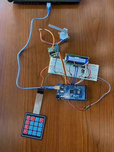
We are also new to using arduino. Here's another picture showing that the LCD does work when the keypad function is commented out of the code and taken out of the 'if' statement in the 'void' loop().

1st off, do not never use the Arduino 5v pin to power a motor.

Ok will do, however, isn’t the stepper motor rated for 5v as it says on the back? It also works fine as it should and has no issues on a side note.

Powering motors form the Arduino board can over load your PC if using a USB cable or cause your voltage regulator to over heat.

Motors should have a power supply dedicated to motors.
In your situation, a common between the Arduino GND and the driver board GND is needed.

Motors can cause electrical noise which can interfere with other devices in the system, your LCD maybe ?

That’s fair, so should we have a power supply that the stepper should be connected to with the common GND?

Also we have tried testing without the stepper and also have created a tinkercad with purely the keypad and the lcd and it still has the Same type of issue with the lcd.

You have a conflict sharing pin 7 in the code.

byte rowPins[ROWS] = {9, 5, 7, 6};

and

LiquidCrystal lcd(2, 3, 4, 5, 6, 7);

As @sterretje said in the previous post.


You can use an external 5v/1Amp power supply connected to your motor driver board.
Connect this same power supply GND to the GND pin on the Arduino.
The Arduino would be powered by the USB cable or power jack.


OR


Connect the motor power supply to the Arduino 5v and GND pins, but then do not use the Arduino power jack or the USB cable.

Also 5 and 6.

... and 2 and 3 and 4.

byte colPins[COLS] = {8, 4, 3, 2 }; 
1 Like

We switched our pins in the code and attached them to the digital pins and this worked! Thank you so much we didn’t think that these pins that weren’t even being used by the keypad, as we only had one pin plugged in for the first column and one for the first row for testing, would have this effect in the code to cause this problem.

We were able to solve the issue due to the conflicting pins in the code, but we were just wondering if this is now correct with the stepper as you were saying? We connected a common ground between the arduino and the stepper, so it’s this proper now?

But they are used by the code which configures all pins of the keypad in a way that is incompaitble with the LCD. You probably can get it to work for two buttons with something like

  const byte ROWS = 1; //four rows
  const byte COLS = 2; //four columns
  const char keys[ROWS][COLS] = {
  {'1','2'},
  }

And the appropriate selection of pins.

Study the library and you have a good chance to find out why they interfere.

This topic was automatically closed 180 days after the last reply. New replies are no longer allowed.