Issue with multiple LSM6DS3 on SPI

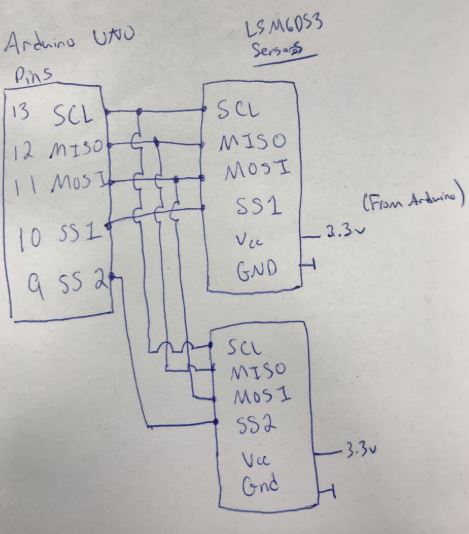
Hello, I am currently having an issue with my 2 LSM6DS3 Accelerometers and Gyro's. I implemented the hardware and software changes for SPI mode. However, when I connect both devices the data is incorrect and only 1 will become active. If only one is connected, then everything works fine. I tried to set the pins HIGH and LOW (this is done in their library already), pull up resistors on my breadboard and via the code, different SS pins and nothing has worked. Any advice and help would be appreciated, thank you.

#include "SparkFunLSM6DS3.h"
#include "SPI.h"

//Create two instances of the driver class

LSM6DS3 SensorOne(SPI_MODE, 8);
LSM6DS3 SensorTwo(SPI_MODE, 6);

int i = 0; // while loop

int val = 0;
int val2 = 0;
void setup() {
  Serial.begin(115200);
  SensorOne.settings.accelRange = 2;
  SensorTwo.settings.accelRange = 2;
  delay(1000); //relax...
  Serial.println("Processor came out of reset.\n");

} // end set up

void loop()
{
  int sTime = millis();
  while (i < 1000) {
    
    Serial.print(i); // print the increment
    Serial.print('\t');
    Serial.println(millis());// - sTime);

    //    digitalWrite(6, HIGH); //turn off Sensor 2
    //    delay(0.2);
    //    digitalWrite(8, LOW); // turn on Sensor 1

    //    pinMode(6, INPUT_PULLUP); //Sensor 2 off

    if ( SensorOne.begin() != 0 )
    {
      Serial.println("Problem starting the sensor with CS @ Pin 9.");
    } else {
      Serial.println("Sensor with CS @ Pin 9 started.");
    } // end else

    Serial.print('\t');
    Serial.print(SensorOne.readFloatAccelX());
    Serial.print('\t');
    Serial.print(SensorOne.readFloatAccelY());
    Serial.print('\t');
    Serial.print(SensorOne.readFloatAccelZ());
    Serial.print('\t');
    Serial.print(SensorOne.readFloatGyroX());
    Serial.print('\t');
    Serial.print(SensorOne.readFloatGyroY());
    Serial.print('\t');
    Serial.println(SensorOne.readFloatGyroZ());

    //    digitalWrite(9, HIGH); // turn 1 off
    //    delay(0.2);
    //    digitalWrite(7, LOW); // turn 2 on

    pinMode(8, INPUT_PULLUP); //sensor 1 off

    if ( SensorTwo.begin() != 0 )
    {
      Serial.println("Problem starting the sensor with CS @ Pin 7.");
    } else {
      Serial.println("Sensor with CS @ Pin 7 started.");
    } // end else

    val = digitalRead(9);     // read the input pin
    Serial.println(val); // gives a '1'

    Serial.println('\t');

    val2 = digitalRead(7);     // read the input pin
    Serial.println(val2); // gives a '1'

    Serial.print('\t');
    Serial.print(SensorTwo.readFloatAccelX());
    Serial.print('\t');
    Serial.print(SensorTwo.readFloatAccelY());
    Serial.print('\t');
    Serial.print(SensorTwo.readFloatAccelZ());
    Serial.print('\t');
    Serial.print(SensorTwo.readFloatGyroX());
    Serial.print('\t');
    Serial.print(SensorTwo.readFloatGyroY());
    Serial.print('\t');
    Serial.println(SensorTwo.readFloatGyroZ());
    delay(0.2);

    i++; // increment while loop
  } // end while
} // end program loop

Post a wiring diagram of your setup. Connecting the LSM6DS3 to the UNO directly might fry the chip. Maximum voltage on the SPI bus is 3.7V, the UNO uses 5V level on it's signal pins.

So I'm using a breadboard for my my sensors, and I've connected the power to 3.3V, and when I measured the voltage it came out correct. The pins also register 43.6mA for one, and 42.7mA for the second. Is it possible the current is not high enough? Also I cannot find my correct boards in Fritzing, will pictures suffice?

So I'm using a breadboard for my my sensors, and I've connected the power to 3.3V, and when I measured the voltage it came out correct.

You cannot measure the voltage with a multimeter, you need a scope to get the short voltage spikes that a bus interface as the SPI generates.

The pins also register 43.6mA for one, and 42.7mA for the second.

I don't know which pins you mean but the Arduino pins must not be loaded with more than 40mA (100mA for the complete board).

Also I cannot find my correct boards in Fritzing, will pictures suffice?

You don't have to use a program for that, hand drawn is sufficient. If you post sharp pictures where every connection is clearly visible, photos are OK too.

Here is the schematic:

I used an Oscilloscope to measure both CS lines, they seem to be fine with both alternating:
TwoCS.JPG

Then I measured only 1 sensor attached: CS and MISO respectively. I achieve 6 outputs for my x,y,z on the accel and gyro:
CsThenMisoOneSensor.JPG

With 2 sensors attached MISO and CS respectively:
MisoCsTwoSensors.JPG

I'm not sure exactly the reason on why the data is corrupted. When both sensors are connected, I I use the serial monitor for feedback and check to see if the CS pins are active and the device has initialized, however it tells me neither are active and the data coming back is garbage. My next step is to no longer use the SparkFun library and implement when the CS pins go high and low myself, along with transferring the data via SPI. It's just that the library obliviously made data collection so much easier.
*Edit was made to re-align the pictures

**Edit: I'm using serial monitor for debugging purposes, however I am going to eventually write to a data file, is serial becoming my bottleneck?

TwoCS.JPG

CsThenMisoOneSensor.JPG

MisoCsTwoSensors.JPG

The last picture shows that the signal levels are at about 3.5V, so there seem to be protecting diodes in the LSM. If you run this setup for a longer time period expect the chips to fail sooner or later.
I still recommend to use level converter.

Interesting are the glitches on the MISO line. I would assume they are to heavy to leave the signal output undisturbed.

Please post a picture of the complete setup, maybe there is another source for interferences.