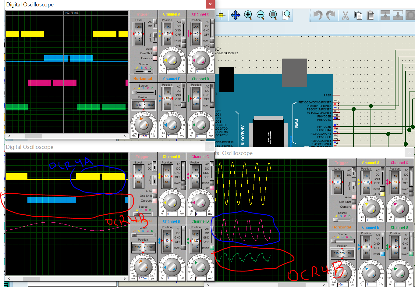
I have tried simulating the code at 40kHz, but when i simulate with Proteus. The OCR4B is not producing the same pulse pattern as with other OCRnA/B. I couldn't understand the observation.
I'm using Timer 1,3 & 4. Lookup table elements - 400.
#include <avr/io.h>
#include <avr/interrupt.h>
#define elements 400                //elements=(half of period of output wave)/(period of switching freq)=((1/2)*(1/50))/(1/50000)
#define switchingfreq 40000

int compare=0;

int m=0;
int i=0;
int j=0;
int k=0;

int phase1=0;
int phase2_1=0;
int phase2_2=0;
int phase3_1=0;
int phase3_2=0;

int sinPWM[elements];
double temp;

void setup(){

  Serial.begin(9600);

  compare = (16*1e6)/(2*switchingfreq);

  /*Generate sine lookup table*/
  for(m=0;m<elements;m++)
  {
    temp=sin(m*PI/(elements-1))*compare;
    sinPWM[m]=(int)(temp+0.5);
  }

  cli();                            //Stop interrupts

  /*Register initilisation for Timer/Counter 1*/

  TCCR1A=0;                         //Reset the value
  TCCR1B=0;                         //Reset the value
  TCCR1A=0b10100010;                //Phase-correct pwm mode, TOP - ICRn
  TCCR1B=0b00010001;                //No prescaler
  ICR1=compare;

  /*Register initilisation for Timer/Counter 3*/
  TCCR3A=0;                         //Reset the value
  TCCR3B=0;                         //Reset the value
  TCNT3=0;                          //Reset the value
  TCCR3A=0b10100010;                //Phase-correct pwm mode, TOP - ICRn
  TCCR3B=0b00010001;                //No prescaler
  ICR3=compare;

  /*Register initilisation for Timer/Counter 4*/
  TCCR4A=0;                         //Reset the value
  TCCR4B=0;                         //Reset the value
  TCNT4=0;                          //Reset the value
  TCCR4A=0b10100010;                //Phase-correct pwm mode, TOP - ICRn
  TCCR4B=0b00010001;                //No prescaler
  ICR4=compare;

  TIMSK1 |=(1 << TOIE1);            //Enable interrupts for OCR5A compare match

  sei();                            //Enable global interrupts

  /*Pins setup*/
  DDRB=0b01100000;                  //Set PB5 (OCR1A) and PB6 (OCR1B) as outputs; based on board pin mapping (could use pinMode to set input/output)
  DDRE=0b00011000;                  //Set PE3 (OCR3A) and PE4 (OCR3B) as outputs
  DDRH=0b00011000;                  //Set PH4 (OCR4A) and PH5 (OCR4B) as outputs
  pinMode(8,OUTPUT);
}

ISR(TIMER1_OVF_vect){               //Interrupt when timer 1 overflows

  if(i<elements && phase1==0)
  {
    OCR1A=sinPWM[i];                //Turns on positive of phase1 pulse; Change duty cycle
    OCR1B=0;

  }
  if(i<elements && phase1==1)
  {
    OCR1A=0;
    OCR1B=sinPWM[i];
  }
  if(i>=elements && phase1==0)
  {
    i=0;
    phase1=1;                       //Enable OCR1B
  }
  if(i>=elements && phase1==1)
  {
    i=0;
    phase1=0;
  }

  i++;
  if(i==((2*elements)/3) || phase2_1==1)
  {
    phase2_1=1;

     if(j<elements && phase2_2==0)
    {
      OCR3A=sinPWM[j];                //Turns on positive of phase1 pulse; Change duty cycle
      OCR3B=0;
    }
    if(j<elements && phase2_2==1)
    {
      OCR3A=0;
      OCR3B=sinPWM[j];
    }
    if(j>=elements && phase2_2==0)
    {
      j=0;
      phase2_2=1;                       //Enable OCR1B
    }
    if(j>=elements && phase2_2==1)
    {
      j=0;
      phase2_2=0;
    }
    j++;
  }

  if(j==((2*elements)/3) || phase3_1==1)
  {
    phase3_1=1;

    if(k<elements && phase3_2==0)
    {
      OCR4A=sinPWM[k];                //Turns on positive of phase1 pulse; Change duty cycle
      OCR4B=0;
    }
    if(k<elements && phase3_2==1)
    {
      OCR4A=0;
      OCR4B=sinPWM[k];
    }
    if(k>=elements && phase3_2==0)
    {
      k=0;
      phase3_2=1;                       //Enable OCR1B
    }
    if(k>=elements && phase3_2==1)
    {
      k=0;
      phase3_2=0;
    }
    k++;
  }
}

void loop() {
  //nothing
}
Thank you.