Hi
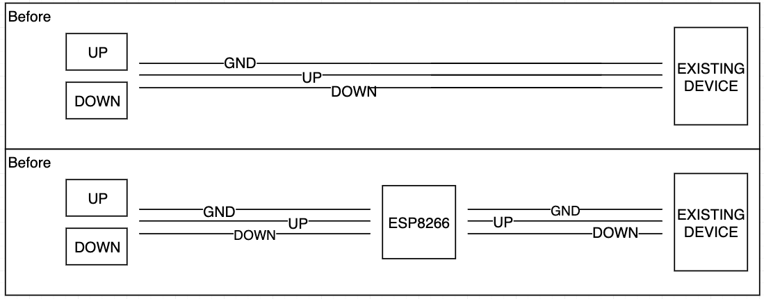
Im trying to place an ESP8266 between an existing device using its existing buttons, and I have managed to read the input from the buttons. I have however problems controlling the output from to the existing device. I have created a diagram of what I am trying to do and attached it to this post.
The code for doing this is quite simple:
#define INPUT_UP 4
#define INPUT_DOWN 5
#define OUTPUT_UP 13
#define OUTPUT_DOWN 12

void setup() {
  Serial.begin(115200);
  pinMode(INPUT_UP, INPUT_PULLUP);
  pinMode(INPUT_DOWN, INPUT_PULLUP);
  pinMode(OUTPUT_UP, OUTPUT);
  pinMode(OUTPUT_DOWN, OUTPUT);
}

void loop() {
  if (digitalRead(INPUT_UP) == LOW) {
    Serial.println("UP");
    digitalWrite(OUTPUT_UP, HIGH);
  } else {
    digitalWrite(OUTPUT_UP, LOW);
  }

  if (digitalRead(INPUT_DOWN) == LOW) {
    Serial.println("DOWN");
    digitalWrite(OUTPUT_DOWN, HIGH);
  } else {
    digitalWrite(OUTPUT_DOWN, LOW);
  }
}
What seems to be happening is that as soon as i connect the output the signal is sent, is there a better way of programatically controlling the output, ie. the connection between the output (UP/DOWN) and GND.
Would appreciate any tips or examples on what I should look at, since im a bit at a loss
I have created a diagram of what I am trying to do and attached it to this post.
Thing is we need a schematic. This diagram, below makes little sense
What are these devices you talk of. Do you know the ESP8266 is a 3V3 device and so can not drive a 5V device?
What size in volts are your input signals? The ESP8266 is a 3V3 device and so will be damaged if the voltage is greater than this.
Both diagrams say before?
What seems to be happening is that as soon as i connect the output the signal is sent,
Yes that is what you have written. How do you expect it to operate? You should not be connecting things while a system is powered anyway.
Yeah, well Im not that experience with hardware projects and thought of giving it a go, and learning a lot in the progress.
I did not find a lot of information about the input signals, but if any I would guess its 5V, Need to borrow a multimeter and find out.
Yeah a forgot to change the text but the lower image is what I am trying to achieve.
Yes that is what you have written. How do you expect it to operate? You should not be connecting things while a system is powered anyway.
Not sure what you meant here, but I do agree that I should not be connecting thing while its powered on, but guess Im just "hacking" a bit on it. What I mean however is that I would hope that it is possible to not have a signal/connectivity on the output signals unless the input is detected? In the code the input is detected when it registers as LOW, so when the input signal is LOW i would like to activate the OUTPUT signal..
However from what seems to be the case the signal is activated regardless if I write HIGH or LOW..
larseen:
I did not find a lot of information about the input signals, but if any I would guess its 5V, Need to borrow a multimeter and find out.
You also need to know how much current flows in the existing circuit when a button is pressed. Microprocessors are only able to deal with very small currents (20 milliamps for an Uno, but I don't know about an ESP8266, I suspect it would be lower). If a larger current is required then some extra components will be required.
...R
What I mean however is that I would hope that it is possible to not have a signal/connectivity on the output signals unless the input is detected?
We are talking about a digital signal here. It is either high or low. If it is not high it is low. There is no such thing as “an input being detected”.
The same goes for the output, it is going to be high or low depending on the input.
What on Earth are you doing? Does the unit in the middle have to regenerate the signal or do you simply want to monitor it and print it out?