Joystick returns wave patterns

I have a joystick in my circuit and it has been returning a wave pattern even though all of the pins on the joystick are connected to my Arduino.
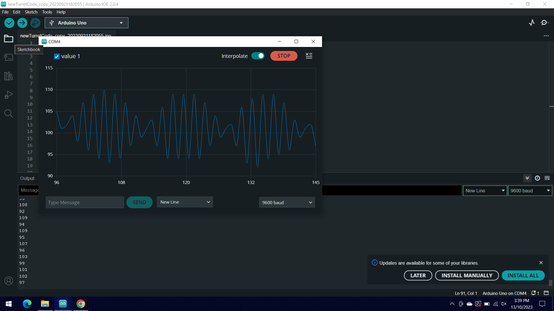
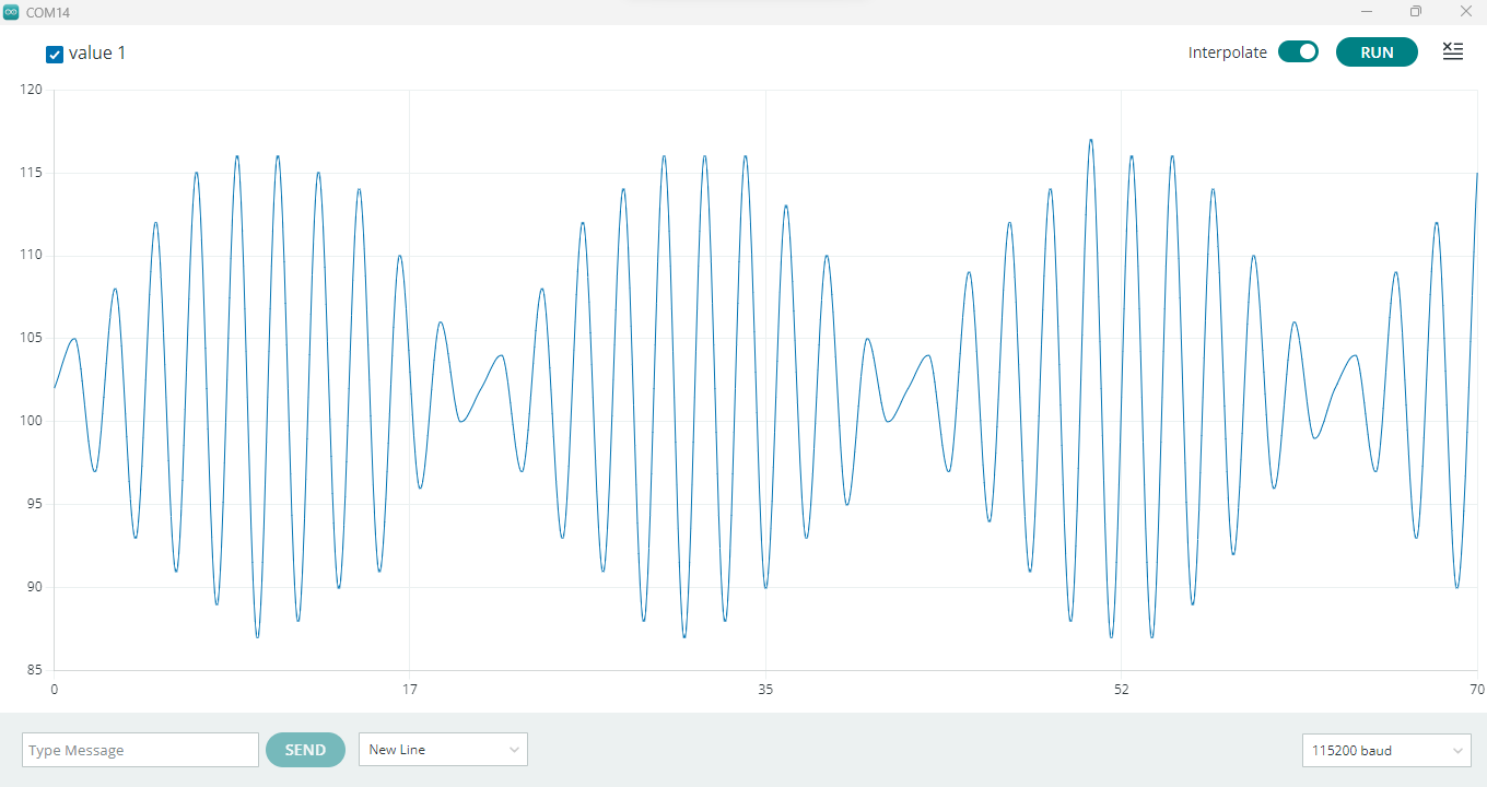
The waves look like this in the serial plotter (with interpolate on):

If you can help me out as soon as possible that would be great! (This is for a school project)

Cheers!

which joystick, which arduino, which code and which wiring exactly?

having a bit of jiggle is not unheard of - if what you have is the result of an analogRead, it's a bit high.

1 Like

Please post the code, the schematic, and some good clear photos of your actual setup.

Have you fitted pull up/down resistors?

My guess is that your wiring is picking up noise at your mains frequency, and that you are not taking analogue reading at a high enough rate to see that it is a 50Hz/60Hz sinewave.
This is known as aliasing.

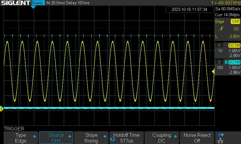
It looks to me as though you have a signal of oround 0.5V with approvimately 50mV of mains hum superimposed on it.

Using a function generator to give a 50Hz, 50mV signal, I can create a similar waveform to yours by taking a sample every 10.5ms. (just over half the period of the input signal).

int inputPin = A0;       
int outputpin = 12;                  // output to oscilloscope
unsigned int raw = 0 ;
unsigned long previousMicros = 0;       
const long interval = 10500;        // sampling interval 10500µs = 10.5ms

void setup() {  
  pinMode(outputpin,OUTPUT);
  Serial.begin(115200);
  }

void loop() {
  unsigned long currentMicros = micros();
  if (currentMicros - previousMicros >= interval) {
    previousMicros = previousMicros + interval;  
    PORTB = B00010000;  
    raw = analogRead(inputPin);
    Serial.println(raw);   
    PORTB = B00000000;   
  }
}


oscilloscope trace: taking samples every 10.5 ms to illustrate aliasing

The code looks like the following:

int joyS = A1;
int joyX = A2;
int joyY = A3;

void setup() {
  Serial.begin(9600);

  pinMode(joyS, INPUT);
  pinMode(joyX, INPUT);
  pinMode(joyY, INPUT);
}

void loop(){
  int vX = analogRead(A2);
  int vY = analogRead(joyY);
  Serial.println(vX);
}

The actual setup looks like:


I'm not sure how well you can see these images.

Hi, @tobiasjburford

What waveform do you get when you use the jotstick?

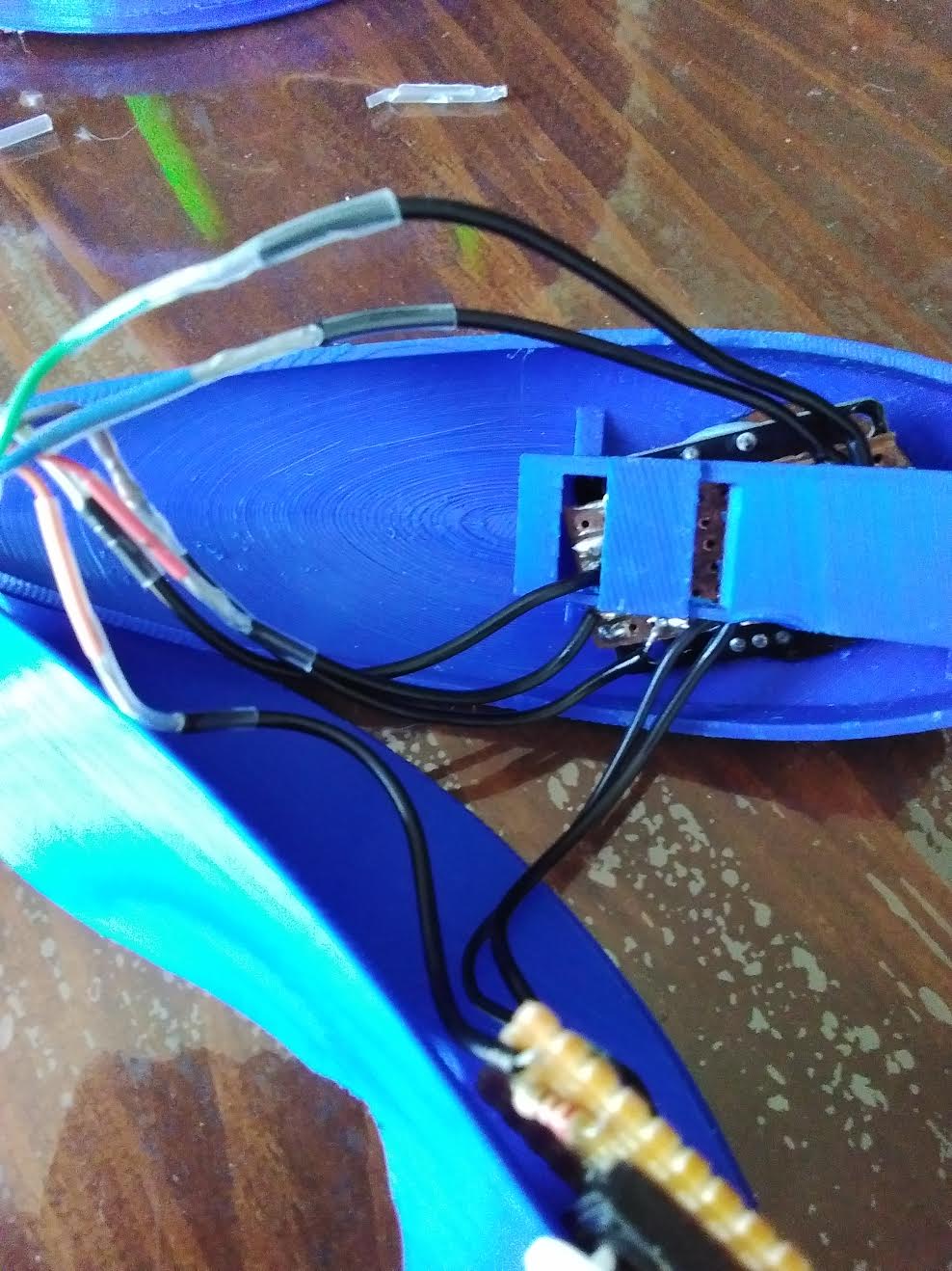
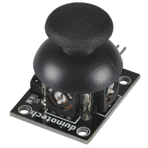
An image of your joystick would be good as well as a link to specs/data?

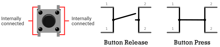
If it is the switching type joystick, rather than the pot type, with the joystick in the middle the inputs to the UNO will be open circuit.

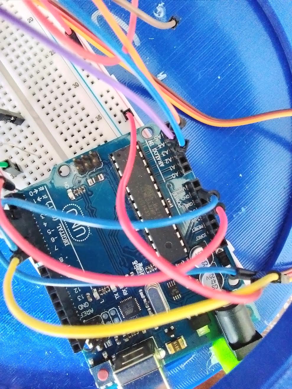
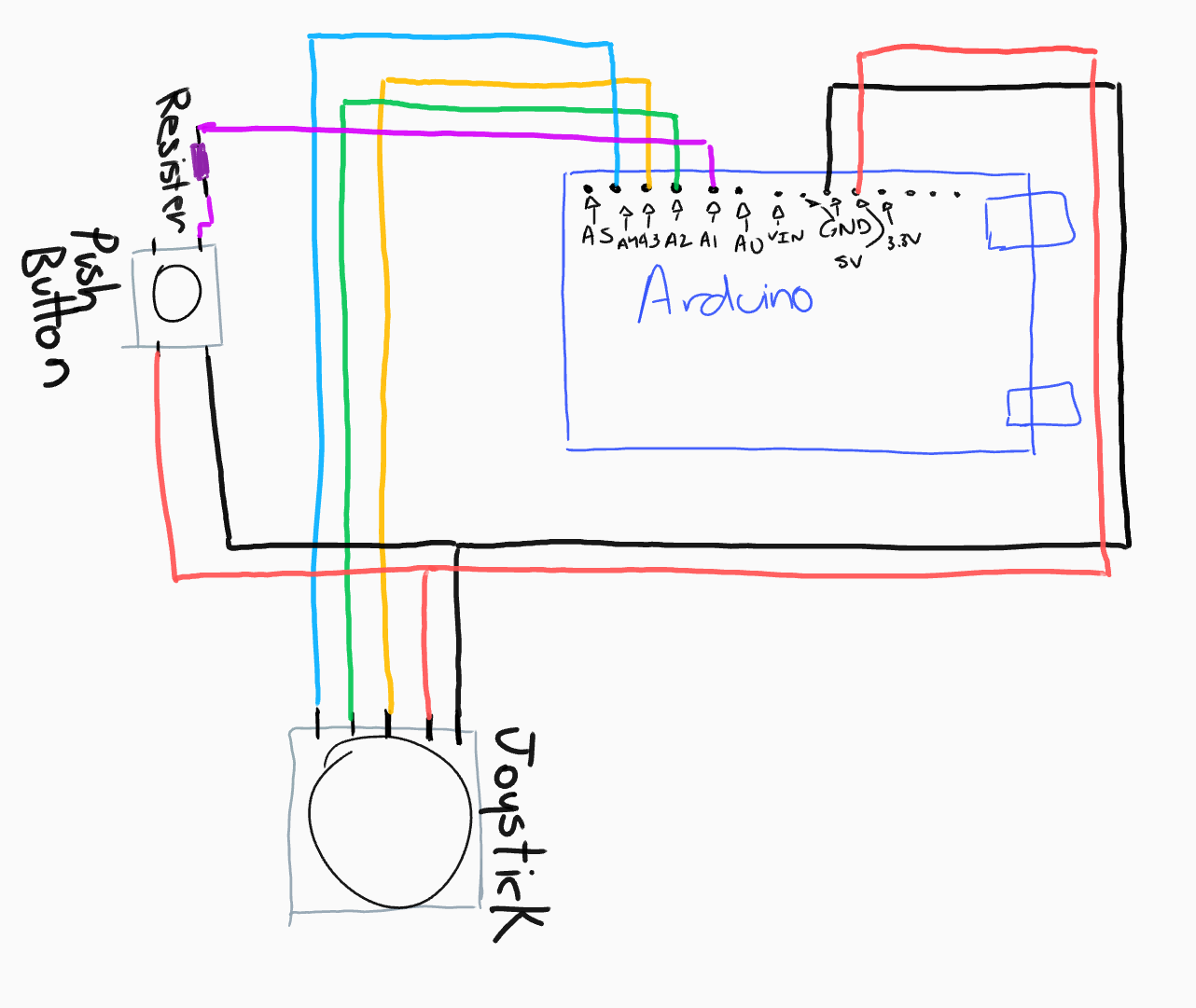
Please get your pen(cil) and paper out and post a copy of your circuit, a picture of a hand drawn circuit in jpg, png?
Hand drawn and photographed is perfectly acceptable.
Please include ALL hardware, power supplies, component names and pin labels.

Do you have a DMM? Digital MultiMeter?

Thanks.. Tom.. :grinning: :+1: :coffee: :australia:

Hey @TomGeorge !
The joystick is one like this:

The circuit looks like:

I do have the wires soldered onto a vero board and then some wires connecting to the vero board, which then connects to a strip of rainbow wire

I do have a Digital MultiMeter

Hi, @tobiasjburford

Okay put the DMM on Volts DC range.
Do not move the joystick.

Measure;

  1. Between A2 and gnd, black probe to gnd.
  2. Between A3 and gnd, black probe to gnd.
  3. Between A4 and gnd, black probe to gnd.

Please on your diagram mark the pin names on the joystick.

Your press button will not work like that.
Try this.

Thanks.. Tom.. :grinning: :+1: :coffee: :australia:

I am unsure what you mean by these statements.

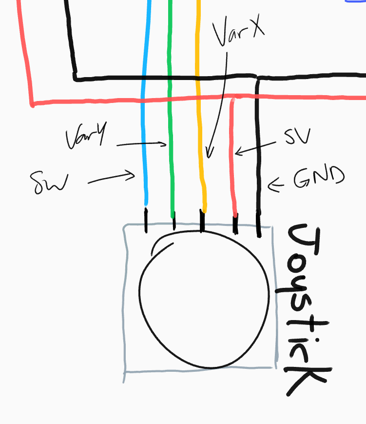
I thought that the 5V had to be the opposite side of the one that is being given to the Arduino and the GND is parallel to the wire that goes to the Arduino.
From what you've drawn on my diagram the wire that goes to the Arduino connects to the 5V with a resister.

The labels added:

keep it dead simple

  • remove the button
  • connect just one joystick to A0 and A1
  • don't connect the joystick switch

run this code

void setup() {
  Serial.begin(115200);
  Serial.println(("A0\tA1"));
}

void loop() {
  analogRead(A0); Serial.print(analogRead(A0)); // double reading to let the voltage stabilize
  Serial.write('\t');
  analogRead(A1); Serial.println(analogRead(A1));// double reading to let the voltage stabilize
}

open the Serial plotter at 115200 bauds and play with the joystick

This does not work, I am given a wider version of the previous issue

Did you use your breadboard?

if you have the kind of long breadboard double check the rails (red and black lines along the sides) are continuous and not stop somewhere in the middle

if you have the gap, then the rails are not continuous so pay attention where you connect the GND for example

can you paste an image of what you see in the Serial monitor ?

can you post better pictures where we see the whole breadboard and wiring?

How far is the joystick from the Arduino?

There is no gap in my red and black lines but I will move the jumpers closer to where I put the ones from the Arduino just in case!

What I see in the Serial monitor looks like:

There are LEDs and servos attached to the breadboard but they are currently not receiving any signals from the Arduino.

The Arduino is in my 3D printing "contraption" so it is difficult to get a good view of the ENTIRE board.

The Arduino is connected to the Joystick with about 1 metre of rainbow wire.

With your DMM.
Place it in volts DC range
Then measure between;

  1. Between A2 and gnd, black probe to gnd and note the reading.
  2. Between A3 and gnd, black probe to gnd and note the reading.
  3. Between A4 and gnd, black probe to gnd and note the reading.

This is with the joystick in the middle position.

Tom... :grinning: :+1: :coffee: :australia:

зображення
do you want shorting Vcc and GND?

that's a great antenna if not properly shielded

are they powered? do the 1m joystick's signals cross the power of the servos?

@tobiasjburford - Is this your power supply? These sometimes have noise problems. Is the problem also with USB power?
powercube

So you want me to have the black probe on the Arduino GND and red one on the A2, A3, A4?

I thought because the ground and signal is on the same side that when you press the button it will give the HIGH from the 5V on the other side (Like in the image), is this not how it happens?

It is just the strip and then some clear heat shrink on the outside, how should it be shielded?

One positive and one ground comes from the Arduino to the breadboard, this has my LEDs, servos and joystick.

It is with USB power coming from my laptop, this is the only power supply I've used

Yes, come back with 3 voltage readings with the joystick in its middle position.

Then do the same with your DMM in Volts AC range.

Thanks.. Tom.. :grinning: :+1: :coffee: :australia: