Keypad 3rd column from top not working

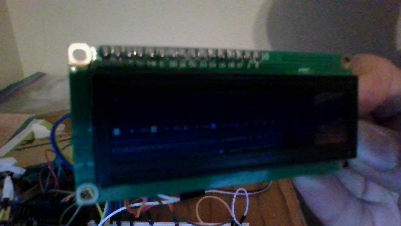
I am working on a safe that unlocks when a certain password is input. It was working fine until I decided to add an LCD screen. Now when I type into the keypad, the 1-6, 0, A, B, and D. I do not need the * or # to appear. I have checked the wiring of the (in this case) 6-pin. This is the pin that (correct me if I'm wrong) controls the column 3rd from the top. I can provide pictures if needed. If you have any suggestions on my code that don't relate to the problem, they are greatly appreciated. Here is the code:

#include <Servo.h>
#include <Keypad.h>
#include <LiquidCrystal.h>

Servo ServoMotor;
char password[4] = {'4', '2', '7', '\0'}; 
int position = 0;
const byte ROWS = 4;
const byte COLS = 4;
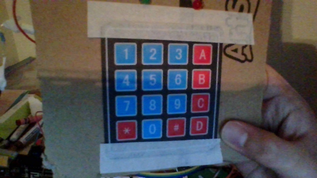
char keys[ROWS][COLS] = {
  {'1', '2', '3', 'A'},
  {'4', '5', '6', 'B'},
  {'7', '8', '9', 'C'}, 
  {'*', '0', '#', 'D'}
};
byte rowPins[ROWS] = { 8, 7, 6, 9 };
byte colPins[COLS] = { 5, 4, 3, 2 };
Keypad keypad = Keypad(makeKeymap(keys), rowPins, colPins, ROWS, COLS);
int RedpinLock = 12;
int GreenpinUnlock = 13;

LiquidCrystal lcd(10, A0, A1, A2, A3, A4);

void setup()
{
  lcd.begin(16, 2);
  pinMode(RedpinLock, OUTPUT);
  pinMode(GreenpinUnlock, OUTPUT);
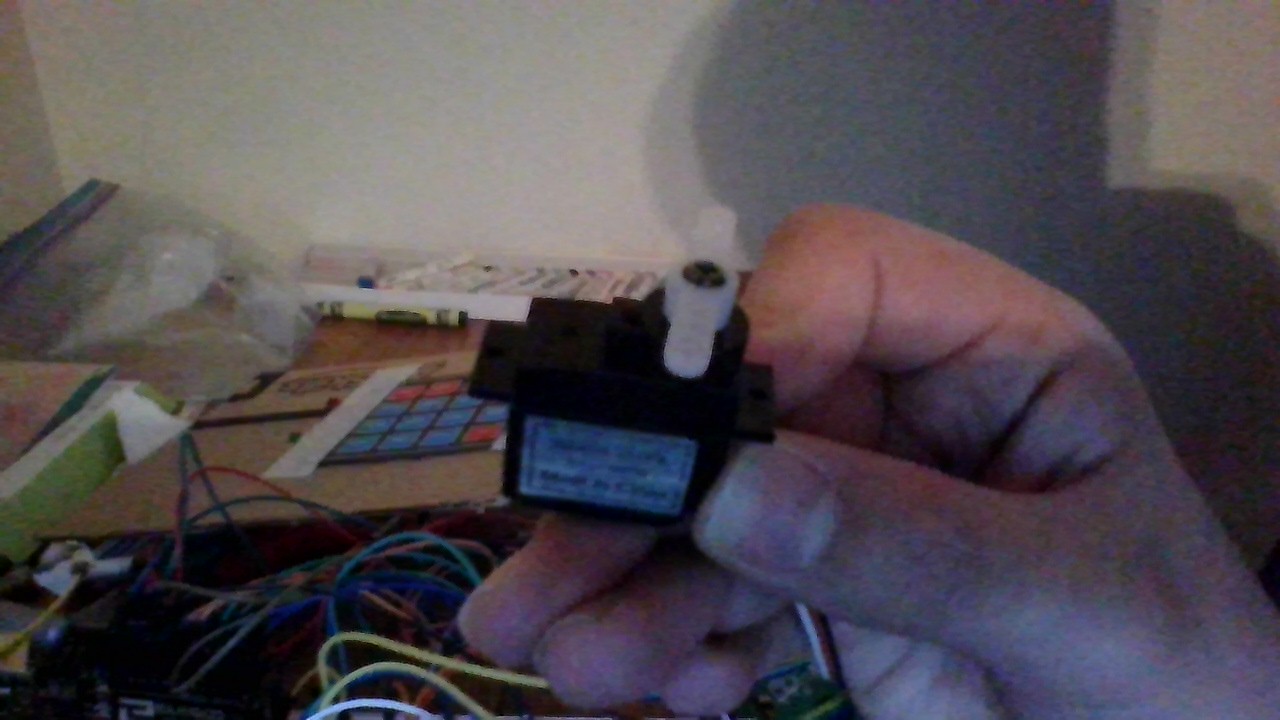
  ServoMotor.attach(11);
  LockedPosition(true);
}

void loop()
{
  char key = keypad.getKey();
  if (key != NO_KEY)
  {
    if (key == '#')
    {
      position = 0;
      ClearPassword();
      UpdateDisplay();
    }
    else
    {
      if (key != '*')
      {
        password[position] = key;
        position++;
      }

      if (position == 3)
      {
        CheckPassword();
      }
      UpdateDisplay();
    }
  }
  delay(100);
}

void LockedPosition(int locked)
{
  if (locked)
  {
    digitalWrite(RedpinLock, HIGH);
    digitalWrite(GreenpinUnlock, LOW);
    ServoMotor.write(11);
    ClearPassword(); 
    UpdateDisplay();
    lcd.setCursor(0, 0);
    lcd.print("Enter PSW:");
  }
  else
  {
    digitalWrite(RedpinLock, LOW);
    digitalWrite(GreenpinUnlock, HIGH);
    ServoMotor.write(90);
    ClearPassword(); 
    UpdateDisplay();
    lcd.setCursor(0, 0);
    lcd.print("Enjoy");
  }
}

void UpdateDisplay()
{
  lcd.clear();
  lcd.setCursor(0, 0);
  lcd.print("Enter PSW:");
  lcd.setCursor(0, 1);
  lcd.print(password);
}

void ClearPassword()
{
  for (int i = 0; i < 3; i++)
  {
    password[i] = ' ';
  }
  password[3] = '\0';
}

void CheckPassword()
{
  if (strncmp(password, "427", 3) == 0) 
  {
    LockedPosition(false);
  }
  else
  {
    lcd.clear();
    lcd.setCursor(0, 0);
    lcd.print("Incorrect");
    delay(2000);
    lcd.clear();
    LockedPosition(true);
  }
}

Thanks!

  • Always show us a good schematic of your proposed circuit.
  • Show us good images of your ‘actual’ wiring.
  • Give links to components.

Ok, sorry this is my first time here, what do you mean give links? I can do the others

  • Web links to major hardware components in your projects.

Do you have any suggestions without those? I am working on the schematic now. I used an LCD screen, a keypad, and a
servo, all provided by my teacher, so I have no links to provide. By the way thanks for helping me get help easier.


The idea is to see good images of the wiring for us to check.

BTW


  for (int i = 0; i < 3; i++)
  {
    password[i] = ' ';
  }
  password[3] = '\0';

Try


  for (int i = 0; i < 4; i++)
  {
    password[i] = '\0';
  }

What happens if you use the sketch that did not have any LCD but did work?

Try that, and then try that as well as disconnecting the LCD.

Adding the LCD shouldn't break anything.

BTW you prolly mean the third row from the top?

What? Just say which keys work and which don't and which you aren't even testing, although you might fix up the LCD-less sketch, or make a version that just tests the keypad by printing the buttons as you press them, all 16.

a7

BTW

  • Print the received button push to confirm code is working as you think it is.

The LCD that is available for the schematic is different from mine, it will look like this ;
image
Mine goes (left to right); VSS, VDD, V0, RS, RW, E, D0, D1, D2, D3, D4, D5, D6, D7, A, K

In the schematic, I will wire it to those, not the ones that are shown on the LCD in the schematic.

Thanks, alto, I meant that all buttons worked except in row 3 (7, 8, 9, and C)

I'm sorry, what is a received button, I'm very new to this.

OK I read your deleted post.

Try changing this temporarily

byte rowPins[ROWS] = { 8, 7, 6, 9 };

to

byte rowPins[ROWS] = { 8, 6, 7, 9 };

and see if the row that doesn't work is because it's on pin 6, or is a broken row.

That kind of thing.

Sounds like a broken wire or one that isn't doing its job.

a7

1 Like
  • When a button is pressed on the keypad, print that button number and its associated ASCII character to the serial monitor.

Thanks, I feel stupid for doing this now but I'm not on a computer that can run Arduino, the schematic is almost done and I will post that and the results when I have them, sorry. I have the program at school and am on a Chromebook that can't download Arduino. Sorry and ill update on the results later. I see what you mean Larry, thanks!

Here is the schematic, sorry it took so long, there's a lot of wires;
image

  • Your Arduino board 5 volt supply is not adequate to power your project.
    If you continue to use it as such, your Arduino may be damaged.
    Also, never connect an inductive load to the Arduino 5v pin.

  • If you are powering the servo from the Arduino 5v pin, do not do this !

  • Does the LCD backlight need a series current limiting resistor ?

So, how would I best remedy this, Should I Wire the servo to the 3.3-volt supply? How do I wire the circuit to provide the necessary power without too much power?

Your Arduino board 5 volt supply is not adequate to power your project.
If you continue to use it as such, your Arduino may be damaged.

All the components have been working fine except the keypad, is this normal, or do they just randomly cut off due to lack of power?

Also, never connect an inductive load to the Arduino 5v pin.

You mean the servo right?

What do you mean by the LCD needing a resistor? I have the potentiometer, that controls the LCD backlight, what else do I need to have? I have the (you can probably see this in the schematic) VSS connected to the ground in the breadboard, and VDD connected to the 5v in the breadboard, these don't have any resistors. It's the A and K to the far right that have the potentiometer. Do I need resistors for the VSS and VDD?

No. Power the servo from an adequate source of 5 volts, like a 10 watt cellphone charger, or a real power supply.

You could also use 4x AA batteries.

For now, disconnect the servo and let's get the keypad and LCD working.

a7

ok, I have about 25 minutes, I was responding to Paul, this is what they said
image

BTW I am on a computer that can run code and upload now

image

I did this, now I know that it is something with the 7 8 9 C row, I will check wiring, and maybe get a new keypad

Im trying a complete rewiring now

1 Like