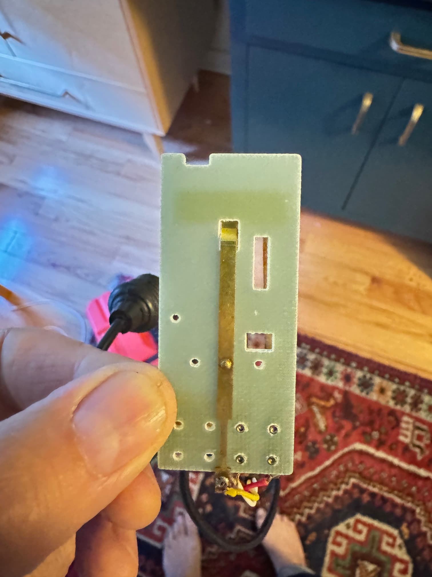
Hoping my newbie request is simple - I am looking for advice on how to use Arduino to automate/trigger the 'forward' function of a Kodak slide projector's remote control which then activates a disslove unit (five pin input to dissolve or projector). I think a simple timed relay will work? I just don't know If I need to make a circuit, which type of relay to use, if I need added power, or if I can just trigger a relay directly from the Arduino to mimick the remote? Attached photo shows the remote control hardware circuit with red wire for forward contact and white for reverse (not needed).
A 5-pin DIN plug is cents, you may decide to ignore the existing remote and cable, and simply plug your controller straight into the socket on the projector.
You simply connect the red and common pins to achieve your functionality.
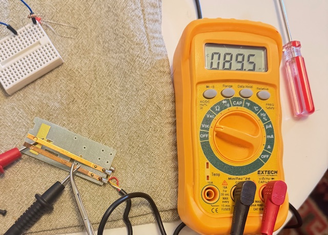
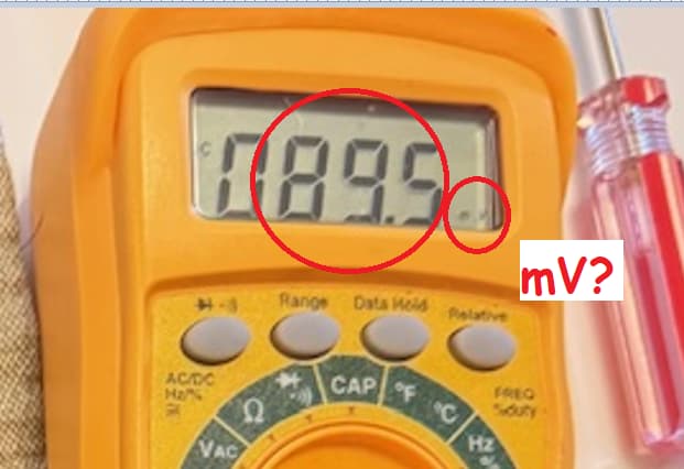
@Paul_KD7HB - Voltage is ~5v DC on those wires - and yes, holding the switch down advances slides forward, but also triggers my dissolve unit between A/B projectors - I would like to automate the forward advance at a timed rate to continuously trigger back and forth dissolves between the two projectors.
@gilshultz - Yes, the function is available at the projector, and I don't really care about the remote (they are easy to source). I think I can just re-wire as needed and keep the 5 pin end to the dissolve unit?
@kmin - Yes, it shows +5V neg to yellow pos to red
@Paul_KD7HB - Yes, when I test the remote I have it plugged into the dissolve unit which is powered on. It is a basic Kodak remote with standard forward/backward function. It can be used either in the projector or in the dissolve unit in my case - it translates same voltage trigger.
You could test it connecting yellow to arduino GND and red to arduino digital pin through ~1000 ohm resistor. Write the pin high , then LOW for 500ms and then HIGH again.
Thanks kmin! I finally got a board to do a test - since I am new to the platform is there a good way to best understand the code I would need to write? I have looked around and asked the Internet, and suspect it is a pretty simple operation, I just don’t know where to begin… I appreciate any guidance!
Start with simple examples. You can always ask help here, but you need to describe well what you are looking for.
Try code to simulate remote button press every 5 seconds:
const int pin = 3;

void setup() {
  digitalWrite(pin, HIGH);   // Preload the HIGH state
  pinMode(pin, OUTPUT);
}

void loop() {
  delay(5000);
  digitalWrite(pin, LOW);    // Set pin LOW
  delay(500);                // Wait 500ms
  digitalWrite(pin, HIGH);
}
@kmin Thank you for taking the time to share this, I will give that a try and see what I can get going.
Just to be specific, I am seeking to emulate the process of manually activating the forward function of a slide projector’s remote control with Arduino. You guys helped me understand the remote passes a 5V current triggering commands to the projector. My goal is to do a quick button push simulation, advancing the slide projector, with a a five second interval between button pushes/voltage triggers.
@kmin I think I got the voltage wrong coming through the remote… I double checked and the current responds as shown with the red cable (triggering forward) as negative and the yellow (ground?) as positive with the white triggering reverse at the same voltage. All that said I couldn’t get the projector to recognize the arduino current either way through the resistor. Any thoughts or advice would be appreciated. Thank you!!
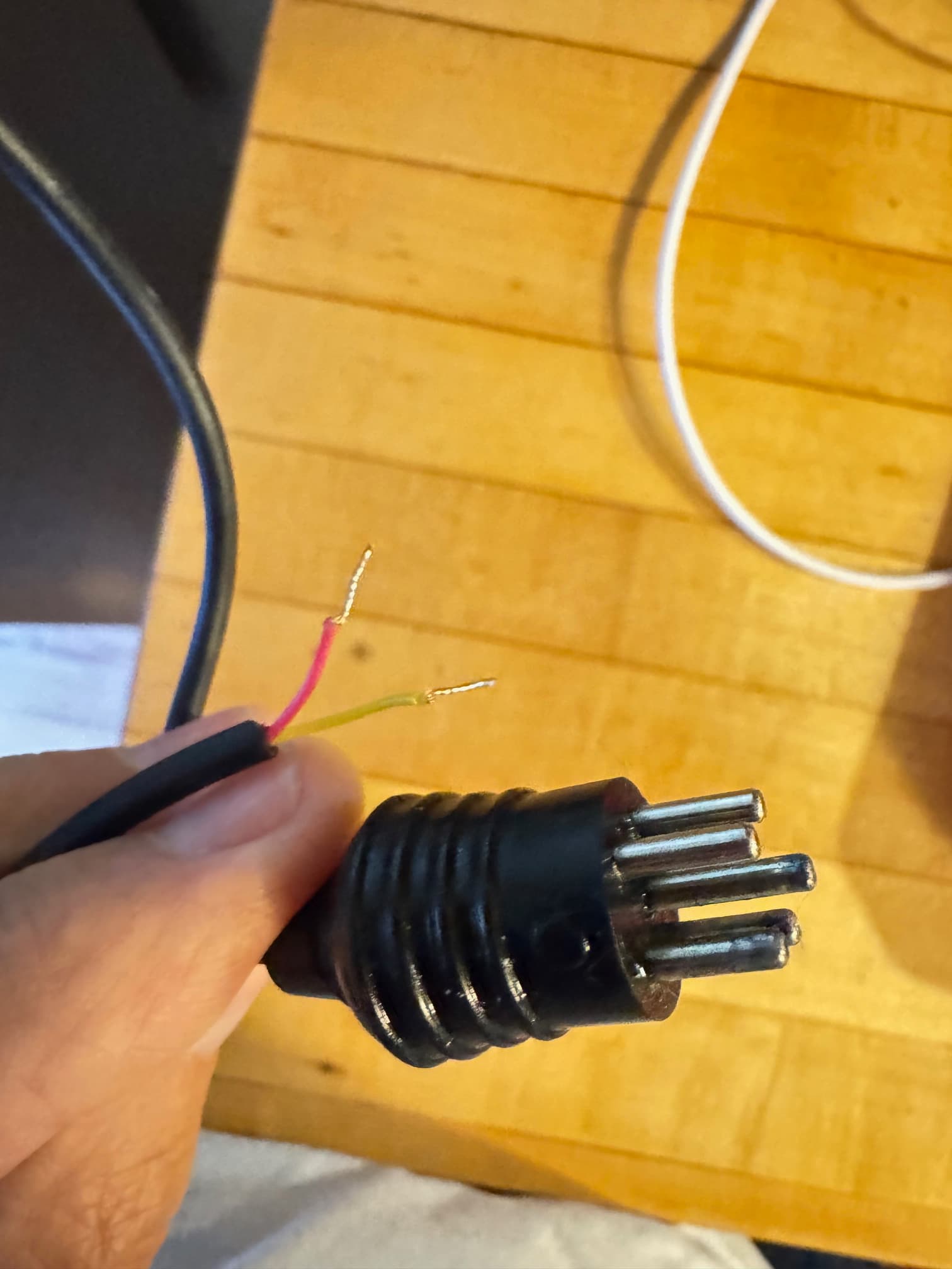
You guys are great! Thank you for your time and interest (patience)! As you can tell I am not very knowledgeable about electronics etc. Doing my best… This is an older-style analogue Kodak slide projector system which uses a basic manually triggered/plugged-in remote control to send the slide carousel forwards and backwards (bypassing the forward/reverse function on the front panel of the proejctor). The remote is a simple contact closure switch with two functions, forward/backwards. Attached here are pictures 1.jpg is the orig. remote guts with the 5-pin connector pins, 2.jpg, the rear of the projector where the pins go, 3.jpg the hacked 5-pin with the two leads that we sussed out are ground and forward (yellow/red) and 4.jpg a circuit diagram for the series projectors I am using - I circled where the remote plugs into the projector and how the circuit flows (not sure if this is helpful at this point) and 5.jpg rear of orig. remote guts. @TomGeorge I can’t seem to get any consistent reading off the contact leads when plugged into the projector and it is turned on - either with the button on/off (open/closed) - the meter jumps all over the place. @kmin Thanks, I will source one of those as well, but will likely need some help with programming…