hi i am working with L298N H-bridge with my DC motor and arduino . but my motor doesn't starts when connected to L298N and if i connected my motor direct with battery it runs . I don't know what is the problem
const int ctrl_rightA = A2;

const int ctrl_rightB = A3;

void setup() {

  // put your setup code here, to run once:

pinMode(ctrl_rightA,OUTPUT);

pinMode(ctrl_rightB,OUTPUT);

}

void Run(void){

  //RUN FORWARD

digitalWrite(ctrl_rightA,HIGH);

digitalWrite(ctrl_rightB,LOW);

}

void loop() {

  // put your main code here, to run repeatedly:

Run();

delay(8000);

//STOP

digitalWrite(ctrl_rightA,LOW);

digitalWrite(ctrl_rightB,LOW);

delay(2000);


//riverse

digitalWrite(ctrl_rightA,LOW);

digitalWrite(ctrl_rightB,HIGH);

delay(8000);

}
so , please let me know how to solve this problem.
You have provided no data on the motor - at a minimum you need the stall current to figure out what power supply and motor driver is suitable. Most motors takes shed loads of current at stall, people usually utterly underestimate this.
The L298 driver is a poor choice at low voltages (less than 24V) as it wastes 3 or 4 volts. It also can only take an amp or so, some motors take 10's of amps.
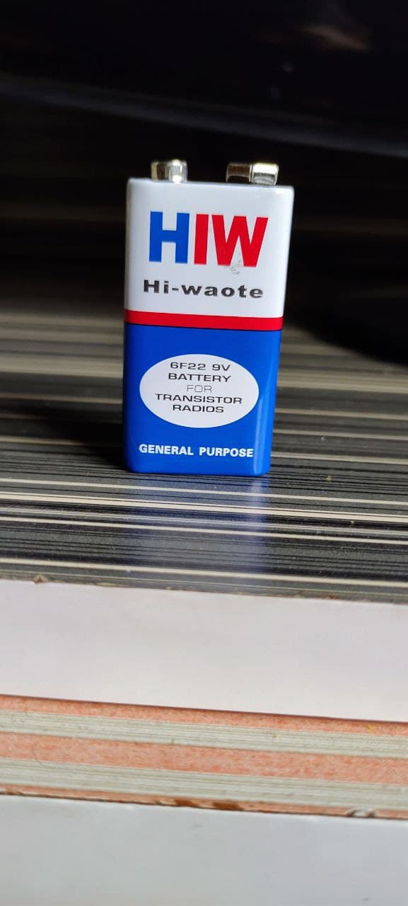
The PP3 sized 9V battery is good for a few hundred mA, unsuitable for all but the tinest of motors (think 1/4 inch diameter motors). Even if such a 9V battery can spin a motor, its likely to droop from 9V down to 3 or 4V and get hot...
Hi,
Are you using the 298 IC on its own or on a module?
Why haven't you got ENA pin HIGH?
VCC pin supplies power to the motor. Voltage anywhere between 5 to 35V can be applied. Remember, if the 5V-EN jumper is in place, you need to supply 2 extra volts than the motor’s actual voltage requirement, in order to run the motor at its maximum speed.
GND is the common ground pin.
5V pin supplies power to the switching logic circuitry inside the L298N IC. If the 5V-EN jumper is in place, this pin acts as output and can be used to power up the Arduino. If the 5V-EN jumper is removed, you need to connect it to the 5V pin on Arduino.
ENA pins are utilized to control the speed of Motor A. Supplying this pin with HIGH logic makes the Motor A rotate, supplying it with LOW logic causes the motor to stop. Removing the jumper and connecting this pin to the PWM input let us control the speed of the Motor A.
IN1 & IN2 pins are used to control the direction of Motor A. If IN1 is HIGH and IN2 is LOW, Motor A spins in a certain direction. To change the direction, make IN1 LOW and IN2 HIGH. If both the inputs are either HIGH or LOW, the Motor A stops.
IN3 & IN4 pins are used to control the direction of the Motor B. If IN3 is HIGH and IN4 is LOW, Motor B spins in a certain direction. To change the direction, make IN3 LOW and IN4 HIGH. If both the inputs are either HIGH or LOW, the Motor B stops.
ENB pin can be used to control the speed of Motor B. Supplying this pin with the HIGH signal makes the Motor B turn, supplying it LOW cause the motor to stop. Eliminating the jumper and interfacing this pin to PWM information let us control the speed of Motor B.
because i tried that also, but nothing worked motor didn't rotate when ENA pin is connected and i saw in youtube videos in which they also didn't used ENA pin . FUNfact :- they were also using 9V power supply still they didn't used ENA pin. so i thought it would be good to follow their methods