L9780 SPI help - inconsistent output

Looks like its specifically SPIF1, which looks like a data fault. What rate are you using? Maybe try slowing your SPI frequency down?

Also, keep in mind according to 5.5 these bits are latched until you send a CLRFLT. Have you tried sending that command and does it still show a SPIF bit set?

Well after walking away and leaving it for 24hours, somehow miraculously it is now performing faultlessly. Very weird, leads me to think i may have some loading issue on my SPI lines. But while it is all probed up and working, I will forge on.

Thank you for your suggestion jungle_jim. All my testing was done at 2.5MHz and was having no luck, but today, weirdly, running at the same speed it all works. I did have a clear fault implementation as I had hoped yesterday at one stage that that was the key to my success but unfortunately not. But it is all working now, so now to wait till it stops to find out what is the fundamental issue.

But looks like now I need to push on through the maths side of things, which I really am not looking forward to.

Just to check in, have any of you involved in this thread gotten a successful working/functioning version of this? I've been slammed up with another project and have not had time to devote to it so it's been sitting for me.

@2mechalec_jack sounds like you had something functioning but were working on the math side; from what I remember that was relatively straight forward. Any luck?

I have been swamped with some other projects...So unfortunately no update here. I have just done some work to the test vehicle for this so, i could potentially jump back onto it later this week.

I've got some time freeing up now that I'm finishing my current project and also have a vehicle with an extra o2 bung (plus an aftermarket WBO2). If you attach/post what you have so far, I can start playing with the testing side of it as well.

Hello all,

I started a project with the L9780 and also have some issues to properly control the Bosch LSU 4.9 probe with this IC. Lack of documentation is a problem and apparently this seems to be the only forum that is actually active. You are probably much more advanced than I am, but I think we can share our problems and discoveries to accelerate each other's development.

My development / issues:

1- Sometimes the SPI message is interrupted without returning the chip select, I send another read message via SPI but no system recover or any error set (only a major drop of RCIMP2). It is probably an error with my SW, but I am trying to set up a recover action. No success so far. nd I cannot find a sequence of codewords to recover the system. Just a clear command doesn't seem to be enough.

This is the SPI this is the error that causes a crash of RCIMP2 (y-axis in counts, x-axis in seconds, probe on bench)

2- AS you can notice previously, I also have this intermittent noise on FV signal. I measured with an oscilloscope and indeed there is noise, the value on the SPI is OK. I suspect it's something with my SW, but I'm still investigating. Have you ever seen anything like this?

3- Sometimes occurs short to battery error (STBS2 and STBS3) and practically RCIMP1 = RCIMP2. This completely messes up my heater control, since the temperature calculation oscillates between 0 and ~2250 degC. When everything is OK, I can maintain 750 degC (300 Ohms).


So far I have only been able to recover from this error with a hard reset on my board (picture). I am trying to find a codeword so I don't have to restart the entire system. Just a clear command doesn't seem to be enough. Have you ever seen anything like this?

4- I have a vehicle available to check L9780 measurements. It uses a linear probe, so I can compare vehicle original measurements vs my measurements. The signal seems to respond well to transients, but is "flattened" to 0.95 < lambda < 1.05, clipping at ~1.32 during a decel fuel shutoff maneuver. Not sure if my calculations are wrong or even a bad codeword could cause that (working with SAMP = 12), it looks like some slope/offset is missing. It looks like some slope/offset is missing. Purple: the noisy FV signal converted to lambda (Ip calculated and lookup on Bosch's table), Red: vehicle's probe.

Sorry for the long post, as I arrived late, I would like to show you what I have at the moment and where I got stuck!

Yeah, it's been a struggle to find good resources on this and seemingly other forums are quiet so i guess we're in the minority here lol.

Just some quick thoughts on your different questions:

1-Any other SPI devices on the bus that may be causing an issue? Also, at the time of the SPI drop-out are the RX'd words "as expected"? IE, looks like you'd be getting a normal response but then it just drops out? Either of those cases may point to some kind of external interference. If not, it'd probably indicate to me that the controller is entering into shutdown or protection, which is why the hard-reset helps recover it. When you said it can't be recovered, can you get the current status of the register yet? Does it indicate any protection trips?

2-The intermittent noise for sure is strange. Looks like to me some kind of switching noise; are you powering this with a bench-top supply or a secondary regulator circuit? Good local decoupling? The FV output should be relatively analog. Just looking at the block diagram its a pure analog signal. The application circuit has an RC filter on it (assuming to help with noise). Do you have that present in your circuit?

3-When is the short to battery occurring (during heatup, normal operation for a period of time, etc)? Also, have you tried a second sensor?

4- Looks like a calculation issue somewhere. You're seeing the same steps/responses/trends but just at a different value. No idea from what/why but it looks to be responding correctly just not giving the expected output.

1- Yes, I have another SPI working together. Today I basically use 2 codewords, one for configuration (0x008407187F7F8040) and another for reading (0x02C407187F7F8040). I am including one with SI echo (REG=1) to check if by chance any of the bits that control the pull downs may be disarming. I am using CLEARFLT = 1 only when any of the fault bits go high, but errors only appear when RCIMP2 < 250 counts. I will do some tests with the heater PWM at a minimum level of around 40%, regardless of the temperature calculation by RCIMP1 and RCIMP2.

2- My guess is a mix between SW and HW, the board measures Lambda (FV) then send this info through the CAN, maybe one IC is interfering with the other IC. The board has its voltage regulator. The board has it own regulator and on the bench I also use a regulated voltage supply. Last bench test, the noise frequence was around 1Hz (no HW or SW change from previous test).


The FV drop was due to a spray of isopropyl alcohol directly on the probe. FV answered as expected.

3- Still under investigation, so far it seems random (phase and operation time). I tried with 2 probes (same part number), also check the probes with a commercial lambda reader based on CJ125. Probes OK.

4- For the calculations I followed the IC datasheet, calculation of FVOUT, total resistance and then lookup in the Bosch table for conversion from Ip to lambda. After I resolve the noise issue in the FV, the plan is to go for testing on the car, maybe see the slope/offset in relation to the car system and reverse engineer the calculation

Some of your responses don't quite line up with the intention of my previous post, so just to clarify a few things:

1-I'd remove the other SPI device to eliminate that as a source for your "random communication drop-outs". Once that issue is resolved (or you can identify the source) then feel free to add the second SPI device back in. Additionally, i was asking what you meant by "no system recover or any error set". It sounded like you can still communicate with the L9780 but just wanted to verify. The intent was that if you could still communicate with the IC that your inability to "recover the system" may be hardware related. That's also why i was asking if you verified the other components and it sounds like you have. So at least that narrows down some of the potential causes.

2-Please look again at the block diagram in the L9780 datasheet. The FV output from the chip appears to be analog in nature; because of that I'd highly doubt it's code/software related noise. Its not going through an internal DAC to provide the output. That's important because it gives a starting point to look for noise. I'd guess that any noise on the FV output is going to be related to some kind of input noise. Maybe that's power related, maybe that's poor local decoupling at the IC, maybe that's the output filter. You haven't given responses to any of those questions.

3-Good you verified the sensors. That rules out any issues in terms of an intermittent internal short.

4-Also I assumed you followed the information in the application notes. That's not the only place in the "calculation" that could be the issue though in your code. There could be overflow issues, order of operations issues, lookup table is incorrect, etc. It's a good sign that the output is following expected patterns/steps but the value being off suggests that there's something not correct in the implementation of the calculation.

Finally back onto this after I respun my PCB after completely balling up the pinouts. Loaded board this evening. Missing a few parts, so have ordered them. Should be back onto the test bench in 3 days. Hope to catchup with everyone and see where they are at.

Well some progress here, board is all assembled and I am back receiving status commands from the device. I have a sensor connected and now just running through getting it to do something.

well that’s good to hear! Have you done anything with a heat-up routine or anything yet or just seeing if the chip will communicate?

For some extra help too, this is some of what I’ve been using to test. I’ve had intermittent issues with this when I was last testing (hence the start of the thread) but maybe some of it will be of help. I’ve got the preliminary PID control in there, as well as a rough try at calculating the Rcell value.

I’ve also tried to put some ā€œtodoā€ flags in there but again, please don’t take this as some "copy/pasteā€ type code. Just hoping maybe there’s a couple nuggets to help along the way.

The overall structure uses a menu over the terminal, that was just so I could query individual commands when I was trying to troubleshoot all of this and see what individual responses were. You can take or leave that but that’s why there’s no like, single ā€œnormalā€ init function that would run through a typical setup of the sensor.

/*  Program is taken from the development firmware but simplified
 *   to menu actions for preliminary debug.
 */

//*****includes
#include <SPI.h>

//*****general defines and data
#define serial_baud       9600          //serial baudrate
#define L9780_SPI_SPD			4000000				//SPI Frequency (8Mhz max per L9780 timing diagram)
#define L9780_SPI_ORDR		MSBFIRST			//define SPI order as MSB first (per L9780 timing diagram)
#define L9780_SPI_MODE		SPI_MODE0			//define SPI mode, clock Idle LOW, first CMD sent w/o SCK (per L9780 timing diagram)
#define L9780_SO_SI       true          //used for "get status" - put the input (SI) register in SO
#define L9780_SO_STAT     false         //used for "Get status" - put the status register in SO

//*****Board specific information
//pn_SPI0_MOSI		        11						//!pinDef: SPI0 master out slave in
//pn_SPI0_MISO		        12						//!pinDef: SPI0 master in slave out
//pn_SPI0_SCK			        13				    //!pinDef: SPI0 clock
#define pn_L9780_CS       10            //!pinDef: chip select for L9780
#define pn_htr_out        9             //!pinDef: manual heater control output
#define K_Rt              452           //look in L9780 application notes for definition
#define K_Rdiv            8851          //look in L9780 application notes for definition

//*****heater control
#define htr_Kp            1
#define htr_Ki            1
#define htr_Kd            1
#define Rcell_tgt         300           //value in ohms
#define Rcell_max         1000          //max value of the cell resistance before enabling current control
#define Rcell_cond        42000         //max value of cell resistance for approx 100*C (end of condensation)
#define PWM_min           0             //PWM lower bound (more on)
#define PWM_max           255           //PWM upper bound (more off)
bool htr_en;                            //global heater enable/disable
uint8_t htr_PWM;                        //heater PWM duty
uint32_t htr_lastRead;                  //last time status was read
int htr_lastErr;                        //last calculated proportinal error

//*****L9780 specific data
#define L9780_rx_reg      0x0800000000000000  //mask to get back the L9780 input register - bitOR
#define L9780_clr_flt     0x0000800000000000  //mask to clear any latched faults - bitOR
#define L9780_RCIMP1      0x0000000003FF0000  //RCIMP1 mask
#define L9780_RCIMP2      0x00000000000003FF  //RCIMP2 mask
#define LSU49_start_CFG   0x00040F18192A8040  //LSU 4.9 start config - non-synchronous mode
#define L9780_VCCS_en     0x0040000000000000  //mask to enable operator - bitOR
#define L9780_STGINRC_en  0x0200000000000000  //mask to enable short to gnd on INRC - bitOR
#define LSU49_control     0x02440F18192A8040  //LSU 4.9 control word - non-synchronous mode

uint64_t L9780_control;                       //current control word
uint64_t L9780_status;                        //current status word

/* Config bit definitions:
 * b63-60 = 0;     not used
 * b59 = REG;      set appropriately when transmitting or receiving
 * b58 = 0;        INRC pull-down (try initially disabled)
 * b57 = 0;        INRC short to ground enable (disable on start)
 * b56 = 0;        INRC gain
 * b55 = 0;        tag resistor network switch (ch1)
 * b54 = 0;        VCCS enable (disable on start)
 * b53 = 0;        VCCS output ch (ch1)
 * b52 = 0;        VCCS pull-down (try initially disabled)
 * b51 = 0;        compensation network (chA)
 * b50 = 1;        VCCS voltage clamp enable
 * b49 = 0;        VCCS voltage clamp switch (ch1)
 * b48 = 0;        VCCS voltage clamp symetry (symetric)
 * b47 = 0;        fault clear (don't clear any faults)
 * b46-43 = 0001;  purge current (-14uA) (taken from L9780 test docs)
 * b42-40 = 111;   FV out gain (12) (taken from L9780 test docs)
 * b39-34 = 000110;VCCS capacitance (assumed Rtag ~130 ohm)
 * b33-32 = 00;    measurement clock period 4MHz
 * b31 = 0;        heater short to battery threshold (250mV)
 * b30-24 = 0011001; RCT1 switch time pulse duration (taken from L9780 test docs)
 * b23 = 0;        operation mode (free-running)
 * b22-16 = 0101010; RCT1 bandgap switch pulse duration (taken from L9780 test docs)
 * b15-14 = 10;    SPI confirmation bits - always 0b10
 * b13 = 0;        not used
 * b12-11 = 00;    heater short to battery fault time (80 Tosc)
 * b10-8 = 000;    INRC switch time pulse duration (taken from L9780 test docs)
 * b7 = 0;         protection FET ch2 (disabled)
 * b6 = 1;         protection FET ch1 (enabled)
 * b5-0 = 0;       not used
 */

void setup() {
  Serial.print(F("Initializing uC.............."));
  Serial.begin(serial_baud);          //start serial. Needed for more than just debug
  
  pinMode(pn_L9780_CS, OUTPUT);       // set the CS pin as an output
  digitalWrite(pn_L9780_CS, HIGH);    // set the CS pin to HIGH (off) 
  SPI.begin();                        // initialize the SPI -> library begin function sets output pins
  
  pinMode(pn_htr_out, OUTPUT);        // heater PWM output
  digitalWrite(pn_htr_out, HIGH);     // turn htr PWM off

  Serial.println(F("Init Complete!"));

  //****display menu
  Serial.println(F("Menu Options"));
  Serial.println(F("--------------------------------------------------------------"));
  Serial.println(F("1)  Init - Send H/W config command to L9780"));
  Serial.println(F("2)  Init - Heatup WBO2 sensor"));
  Serial.println(F("3)  L9780 - Enable VCCS (start operation)"));
  Serial.println(F("4)  L9780 - Enable stgINRC (start closed-loop L9780 control)"));
  Serial.println(F("5)  L9780 - Clear latched faults"));
  Serial.println(F("6)  L9780 - Get SI register"));
  Serial.println(F("7)  L9780 - Get status register"));
  Serial.println(F("--------------------------------------------------------------"));//bookend lines
  //****end display menu
}

void loop() {
  Serial.print(F("Please Enter a Selection: "));
  while (Serial.available() == false){
    //!TODO: enable heater PID control once confident
    //htr_PIDupd();             //maintain heater control
    //htr_calc_Rcell();           //just calculate and display current cell resistance for now
    //!TODO: check for max cell resistance to prevent damage. turn off sensor if above value.
    delay(250);                
  } //wait for user input
	int menu_choice = Serial.parseInt(SKIP_ALL);  //get user input
  Serial.println(menu_choice);

  char c[150];                          //char string for menu outputs
  switch (menu_choice){
    case 1:
      L9780_control = LSU49_start_CFG;
      L9780_SPI_xfr(L9780_control);                     //set initial config values over SPI
      break;
    case 2:{
      htr_en = true;                                    //enable heater operation
      htr_initHeatup();                                 //heat-up sequence
      //!TODO: enable heater PID control once confident
      //htr_PIDupd();                                   //start heater control
      htr_calc_Rcell();           //just calculate and display current cell resistance for now
      }break;
    case 3:
      L9780_control |= L9780_VCCS_en;                   //enable VCCS (start operating)
      L9780_SPI_xfr(L9780_control);   
      break;
    case 4:
      //!TODO: check for max cell resistance to prevent damage.
      L9780_control |= L9780_VCCS_en;                   //enable INRCSTG once started
      L9780_SPI_xfr(L9780_control);
      break;
    case 5:
      L9780_SPI_xfr(L9780_control | L9780_clr_flt);     //clear any latched faults
      break;
    case 6:{
      uint64_t d = L9780_get_status(L9780_SO_SI);       //get current input reg as output
      Serial.print(F("SI Reg (64b): 0x")); SerialPrint_u64(d, true);
      }break;
    case 7:
      poll_L9780status();                               //get current status as output
      Serial.print(F("Status Reg (64b): 0x")); SerialPrint_u64(L9780_status, true);
      break;
    default:
      Serial.println(F("Input not recognized, please enter a valid number"));
      break;
  }
  Serial.println(F("--------------------------------------------------------------"));//bookend lines
}

/*  FUNC:   Serial Print unsigned 64b value
 *  DESC:   Fucntion prints an unsigned 64b wide value
 *  ARGS:   v   - value to print
 *          nl  - true/false to print a new line
 *  RETN:   none
 */
void SerialPrint_u64(uint64_t v, bool nl){
  char c[] = "00000000"; //temp byte to print
  sprintf(c,"%08lX", (v>>32)); Serial.print(c);
  sprintf(c,"%08lX", v); Serial.print(c);
  if(nl){Serial.println();}                         //if selected, print newline
  return;
}

/*  FUNC:   L9780 SPI transfer
 *  DESC:   Fucntion sends a SPI command and receives its result
 *  ARGS:   d	-	data being sent on a SPI transfer
 *  RETN:   spi_buf	- data result
 *	NOTES:	Calls "begin transaction" before every send to ensure
 *					that if another SPI library is being used that updates
 *					these values, that they're appropriately set for L9780
 *          
 *          L9780 expects the MSB first. To ensure that endianess is
 *          preserved, incomming data is transferred to local array
 *          to ensure that MSB is the first byte transmitted
 */
uint64_t L9780_SPI_xfr(uint64_t d){
  uint8_t spi_buf[8];                               //temp array for data to send

  for(uint8_t i = 0; i <8; i++)                     //shift data into temp array
    {spi_buf[i] =  d>>(56 - (i*8));
    //Serial.print("In data | index ["); Serial.print(i); Serial.print("] : ");Serial.println(spi_buf[i],HEX);    
    }
	
	//SPI transfer
	SPI.beginTransaction(SPISettings(L9780_SPI_SPD, L9780_SPI_ORDR, L9780_SPI_MODE)); //start SPI transaction
	digitalWrite(pn_L9780_CS, LOW);  									// set the CS pin to LOW (on)
  SPI.transfer(&spi_buf,sizeof(spi_buf));           //pass address of temp data + size
	digitalWrite(pn_L9780_CS, HIGH);  								// set the CS pin to HIGH (off)
	SPI.endTransaction();															//end SPI transaction

  //TODO: shift back into 64b result

  uint64_t rtrn_data = 0x0;
  for(uint8_t i = 0; i <8; i++)                     //shift arracy back into result
    {rtrn_data |= (uint64_t)spi_buf[i]<<(56 - (i*8));
    //Serial.print("Out data | index ["); Serial.print(i); Serial.print("] : ");Serial.println(spi_buf[i],HEX);
    }
  
  return rtrn_data;                                 //return rx'd data from L9780
}

/*  FUNC:   L9780 Function - Get status register
 *  DESC:   Fucntion reads the current status register
 *  ARGS:   act - true/false to select what is in SO
 *                  true - RX'd data (current SI)
 *                  false - status register 
 *  RETN:   d - SO register
 *  NOTES:  After sending data, per the datasheet the
 *          next SPI frame will have the associated data
 *          in the SO depdending on the asserted REG bit.
 */
uint64_t L9780_get_status(bool act){
  uint64_t d;                                         //temp data word
  
  if(act == L9780_SO_SI){                             
    L9780_SPI_xfr(L9780_control | L9780_rx_reg);      //request input reg back
  }
  else{                                               
    L9780_SPI_xfr(L9780_control);                     //request status reg back
  }
  
  d = L9780_SPI_xfr(L9780_control);                   //read result
  return d;
}

/*  FUNC:   poll status of WBO2 controller
 *  DESC:   Fucntion reads the current status register
 *          and updates the global word.
 *  ARGS:   none
 *  RETN:   none
 *  NOTES:  making this as its own function since it's called
 *          regularly.
 */
void poll_L9780status(){
  L9780_status = L9780_get_status(L9780_SO_STAT);
}


/*  FUNC:   heater function - initial sensor heatup
 *  DESC:   Fucntion called on sensor initialization
 *          and controlls the initial heatup cycle, including
 *          the condensation and ramp phase.
 *  ARGS:   none
 *  RETN:   none
 *  NOTES:  PWM out from L780 is inverse from arduino output
 */
void htr_initHeatup(){
  Serial.println(F("-----Starting Sensor Heatup----"));
  Serial.println(F("---Condensation Phase"));
  htr_PWM = 211; analogWrite(pn_htr_out, htr_PWM);  //condensation stage
  Serial.print(F("HTR PWM %: "));Serial.println(htr_PWM*20/51);
  //!TODO: enable temperature check once confident
  //while(htr_calc_Rcell()<Rcell_cond){}              //wait for end of condensation phase
  delay(11000);                                     //simplified wait for ~20s total for condensation stage to be done
  Serial.println(F("---Condensation Phase End"));

  htr_PWM = 76;                                     //start ramp phase, start at 70% duty (approx 8.4V)
  while(htr_PWM > 0){                               //increasing by 2/255 every 250ms is approx 0.4V/s for ramp phase 
    Serial.print("HTR PWM %: ");Serial.println(htr_PWM*20/51);
    analogWrite(pn_htr_out, htr_PWM);               //set PWM
    delay(250);                                     //ramp rate
    if(htr_PWM >=2){htr_PWM -= 2;}                  //increase/ramp
    else htr_PWM=0;
  }
  
  Serial.println(F("-----Sensor Heatup Complete----"));
  return;
}

/*  FUNC:   heater function - update PID control
 *  DESC:   Fucntion checks/updates current heater PWM value
 *          based on the current cell resistance and adjusts
 *          accordingly
 *  ARGS:   none
 *  RETN:   none
 *  NOTES:  remember the PWM is inverted at the L9780, so to INCREASE 
 *          the heater time (heat up more) the PWM duty must go DOWN. 
 *          This results in a target-actual term. If target < actual, 
 *          then it should be cooled down, and PWM increased which is 
 *          a positive term (so target-actual > 0) and vice-versa
 */
void htr_PIDupd(){
  if(!htr_en) //heater operation disabled. Turn off and return from function
    {htr_PWM = PWM_max; return;}

  int htr_PRP;                  //!heater control PID: proportional term
  int htr_INT;                  //!heater control PID: integral term over time
  int htr_DRV;                  //!heater control PID: derrivative term over time
  int tmp_PWM;                  //temp PWM allows for bounds checking
  
  uint16_t Rcell_crnt = htr_calc_Rcell();             //current read cell resistance
  int htr_Err = Rcell_tgt-Rcell_crnt;                 //calculate current error  
  int de = htr_Err - htr_lastErr;                     //calcuate change in error
  htr_lastErr = htr_Err;                              //update the last error for next update
  
  uint32_t htr_crntRead = millis();                   //get the current timestamp
  uint32_t dt = htr_crntRead - htr_lastRead;          //calculate elapsed time
  htr_lastRead = htr_crntRead;                        //update the last read for next update
  
  //calculate PID terms
  htr_PRP = htr_Kp*htr_Err;
  htr_INT = htr_Ki*htr_Err*dt;
  htr_DRV = htr_Kd*(de/dt);
  
  tmp_PWM = htr_PRP + htr_INT + htr_DRV;              //calculate new heater PWM
  if(tmp_PWM > PWM_max)       {htr_PWM = 255;}        //upper bound clamp
  else if (tmp_PWM < PWM_min) {htr_PWM = 0;}          //lower bound clamp
  else                        {htr_PWM = tmp_PWM;}    //within range, update
  htr_lastErr = htr_Err;                              //update heater error for next term
  return;
}

/*  FUNC:   heater function - calculate cell resistance
 *  DESC:   Fucntion calculates the cell resistance and
 *          updates the global vars
 *  ARGS:   none
 *  RETN:   cell resistance in ohms
 *  NOTES:  none
 */
uint16_t htr_calc_Rcell(){
  poll_L9780status();           //update global with latest status

  //!TODO: verify ADCi vs ADCf and RCIMP1 vs RCIMP2. ADCi > ADCf
  uint16_t ADCi = (uint64_t)(L9780_status&L9780_RCIMP1)>>16;
  uint16_t ADCf = (uint64_t)(L9780_status&L9780_RCIMP2);
  uint16_t d_ADC = (ADCi - ADCf)/ADCf;   //common term, difference in ADCi vs ADCf
  uint16_t tmp_Rcell = (K_Rdiv*K_Rt*d_ADC)/(K_Rdiv - K_Rt*d_ADC);
  
  Serial.print(F("ADCi: ")); Serial.println(ADCi);
  Serial.print(F("ADCf: ")); Serial.println(ADCf);
  Serial.print(F("Cell Reistance: ")); Serial.println(tmp_Rcell);
  
  return tmp_Rcell;
}

Yeah, this is not a fun device to work with!

After a few hardware issues which were my bad.. (like using a 250V mosfet instead of a 30V mosfet which was triggering the heater to battery error) i have finally got no errors and I can ramp my heater.

Edit (for others debugging this issue):
In my case, I accidently used an STD17NF25 on the heater drive, when what I really needed was an STD17NF03. The characteristics of the 25-device make it a poor fit for the L9780 as a low-side heater switch.

Here’s why: the STD17NF25 is a 250 V, non-logic-level MOSFET with (1) relatively high Rds(on) and (2) a large gate charge. Both of these defeat the L9780’s internal diagnostic, which checks whether the heater line has been pulled low after the MOSFET is asserted. At normal heater currents, the higher Rds(on) keeps the drain voltage above the 250/450 mV thresholds, and the large gate charge means the line falls slowly instead of clamping hard to ground. The L9780 sees this and interprets it as a short to battery fault, even though the MOSFET is technically switching.

More generally: if the external MOSFET has too high a gate charge or overall drive requirement, the L9780’s gate driver can’t bring it into saturation quickly. The heater line then decays slowly instead of pulling down sharply. Internally, the L9780 compares the heater pin voltage against two programmable thresholds (ā‰ˆ250 mV and 450 mV). If the voltage doesn’t drop below the selected level within the diagnostic sampling window, it concludes that the FET hasn’t switched correctly and flags a fault.

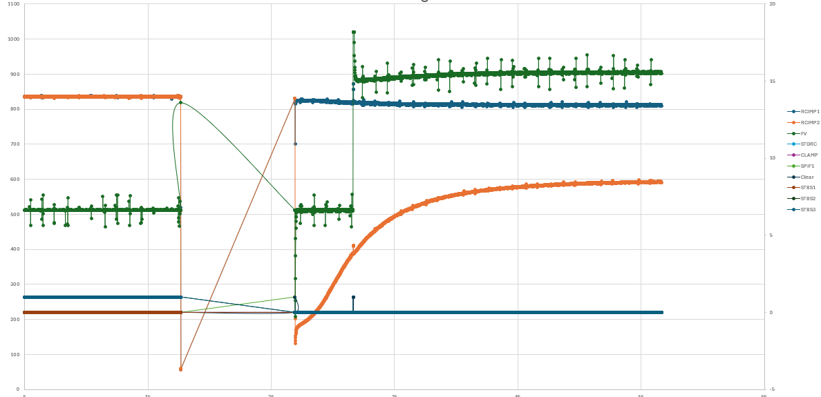
The attached capture shows this exact behavior when using the STD17NF25 — a high-voltage MOSFET with relatively large gate capacitance — instead of the more suitable STD17NF03.

Lesson learned: with the L9780 heater driver, always use low-voltage, logic-level MOSFETs (e.g. ≤40 V rating, low Rds(on) at Vgs = 5 V, and modest gate charge/Qg). High-voltage, non-logic-level parts will almost always trip the ā€œshort to batteryā€ diagnostic, even if they appear to switch.

I did however have SPI issues first thing this morning but that seems to have resolved with no changes which is truly bizarre.

I ended todays efforts ramping my heat and watching the RCIMP registers but they tended not to change much at all. Seemly hovering between 0 and 30 with no linear increase with temperature. One minute they RCIMP1 is at 30 and the next its at 0.

I walked away for a coffee and now every time i talk to the device its telling me i have a STBS3 and STBS2 error… Which was not there before and every time, immediately after a power up I’m hit with it. I think it would be only fitting if I then developed a sudden onset of SPI issues that then miraculously cleared up.

Im stepping away before I smash away! :slight_smile:

What’s your SPI bus frequency? Seems so weird that you’re having such intermittent SPI issues. Post your board design just to check if there’s anything weird going on? At the speeds that this is expected to run at I wouldn’t think there’s an issue at all but…sometimes weird things happen.

Managed to squish a few more hardware issues today but Im still plauged with this SPI communication issue which is really driving me insane.

I have SPI lines running from micro to L9780, i have provision for series resistor and also cap if needed for super high frequency stuff. Havent loaded caps and also tried a combination of low resistance values for my series resistors.

However, it seems that no matter the speed I run, the same issue is still present. If I run at 8.5Mhz or 300kHz, I see the same fault:

With my logic analyzer attached here is a screen grab. It first shows me issuing 64bits with Reg bit set to 1, so that the following frame it echoes the response. As can be seen the second frame (64bits) echoes my first frame, but there is one bit the difference. I send 0x0800 and it always received 0x0860. I can run this many different times and i can almost certainly rule out it synchronizing with some form of interference that it affects the same bit in every transmission.

Maybe another set of eyes would help!
I have even changed L9780 device hoping it was just a beat up chip. But problem still lingers.

So it seems i have either found a quirk of the chip or I just havent read something correctly. But I can prove that it is getting the right data, because if I hold the chip select low the entire time and then punch the second frame of 64bits, i Can see my first frame come out the MISO.

So this leeds me to believe I have some state issue going on rather than a genuine SPI issue.

HAH! You made me realize that I probably made the same mistake in my code initially with this post…. Full disclosure i haven’t made a full SPI device driver before from scratch so I think in my initial implementation I made the mistake and then didn’t realize it. Just never had time to hook up to a logic analyzer when i got involved with other stuff so….i missed it.

So your first screen grab is not typical for SPI devices for an ā€œinstruction with readā€. Usually for the ā€œfull transactionā€ with the peripheral the CS line is held low. Once you toggle the CS high again, it’ll recognize after a period of time that ā€œhey I’m done talking with the controller nowā€ and some will reset their internal state machine then. Similarly then, when the CS line is pulled low again that recognizes the data as a new SPI transaction then.

Your second screen grab is much more expected with a typical SPI transaction. Figure10 in the datasheet lists the same thing, but…..as with most of the datasheet its not every explicit in that the shown data transfers aren’t just for a daisy chaining configuration.

Some companies/devices/authors are better at this than others but to borrow from the MCP2515, you can see a similar interaction. This particular chip holds SO high until the instruction is finished but I’ve seen some as similar ā€œdon’t careā€ during the instruction phase on the SO line:

This figure from the MAX11200 sheet shows that a bit better (this may not be the BEST example since it uses the ā€œDOUTā€ pin for some other indications but you can see where it transitions from ā€œdont careā€ to actual data bits on click edges):

So in short, I think your first example shows just incorrect SPI communication but someone should check me on that since it’s not my forte (and likely one of the issues i had to begin with!). In your first example where the CS line toggles, I think that first 64b word from the peripheral is just junk data. I don’t know for sure if its supposed to represent anything but I’m guessing not. Your second example then I think proves that you’re getting good communication and it’s doing what it should.

Another great test would be to hold CS low, send an instruction with the ā€˜REG’ bit set, CHANGE that instruction (but leave ā€˜REG’ set) and send a second NEW instruction and then finally send another 64b word of dont-care; when done you can set the CS high again. The goal would be to see if both of your sent instructions are echoed back on the MISO line.

image

Similarly, you could do a transmit of [set with REG], [get status], [set with REG], [dont care] and see if it echos back some kind of status word but the important part would be seeing the input register echoed back after that:

image

Alrighty, back with a clear mind and less frustration and im now talking to the device and we are not having the same arguments.

My SPI communication was legit:
In summary:

  • Hold down the chip select
  • Pump 64 bits over the MOSI (This is your control word or SPI Input as per datasheet).
  • Simultaneously the device pumps out 64 bits on the MISO line. The device will output its status if the REG bit in the last control word you sent (prior to this chip select going low) was 0. If the REG bit was 1, it will send an ā€œechoā€.
  • You release the chip select.

If you had multiple L9780 devices daisy chained together then you wouldn’t release the chip select you would keep pumping as many control words as you have daisy chained devices. This is out of scope for most of us here just trying to get one device to be happy. So lets not jump down that rabbit hole.

Where the datasheet is not entirely accurate is the term ā€œEchoā€. Its not an echo of what you sent to it, its an echo of its internal control word register. If the device is in a fault state, this can be different to what you previously sent it.
If you are not in a fault state then the 64bits returned would be what ever you sent it last.

Where I went wrong.
The L9780 device doesn’t have a reset line and requires full power down to get a clean, virgin part. I was actually powering up the board, the micro would start talking to the L9780 and then it would start to ramp the heater and enable pump currents. I would then start my debugger and my JTAG would then tag on and reset the microcontroller chip. Now, it would reset the micro, but it wouldnt change the state of the L9780.

I would then start talking to the L9780 like it was a fresh boot however the device had already been online and running and now I was sending it 0’s in places where I had originally sent 1’s. E.g charge pump run and alike. The L9780 would go into a fault state and the ā€œechoā€ is actually the valid control word it had internally before I started changing what I was sending to it.

So to get around this I now have to tell the device to ā€œGo Liveā€. So when I add power to my board, I dont start talking to the L9780 until I receive the Go command. This means I can plug the board in, the L9780 is a virgin part, I can then use my JTAG , reset micro then start communicating with my control words and it is happy. I always power down completely after a ā€œsessionā€, i probably could implement a state machine to take it back offline, but for now it works.

Moral to the story: Don’t go live, reset your micro and think that the L9780 will be happy about you pretending to talk to it like its a fresh boot.

Hope that makes sense…let me know if im not clear.

For others playing along at home, find attached a valid SPI transaction. If you look at the first byte 0x33 on the MISO, that first 3 is the version of the chip. You can also validate the CB bits in both my sent control word and the received status. Note in my control word, I have set the REG bit, cause the next time I pump the CS line, i would like to get the ā€œEchoā€ back.

Glad it sounds like things are working, but just a couple questions/comments. Not trying to be pedantic here but I feel like since we’re sorting this out that its important to clarify/be specific so there’s no assumptions or miscommunication.

  1. when i was talking about the timing diagram, you’re correct that figure 10 shows multiple devices daisy-chained together but the diagram is just showing how the various commands cascade through the different MISO/MOSI lines when they’re all held low by the same CS. Really the other devices can be ignored and just look at the ā€œL780_1ā€ lines.

  2. the datasheet specifically says that with the REG bit set to 1 that the response should be the input register, not any kind of internal control word. I agree it’s odd though from your previous timing shots that regardless of whatever the datashseet says that the same word should have been sent back with REG=1, regardless of what kind of ā€œfault stateā€ the chip might be in.

Also i thought there was a way to reset the chip with a control word? I’ll have to go back and dig through that. I know there’s a power-on-reset functionality to it but I’d be surprised if the ONLY way to reset the chip is a power cycle. If it is though, that’s some decent insight where any proper control circuit would need an external FET for the uC to control as a hard reset for the L9780

Coming back to this, combing through the datasheet I wasn’t able to find anything specific to a ā€œstate resetā€ other than the timing state that’s used for the A/D conversion. There is the ā€œclear faultā€ command which i’d assume would also trigger some kind of refresh but like already mentioned, there seems to be no like ā€œhard resetā€ associated with it.

Also, re-visiting my #1 above, it still does appear now that even when re-asserting the CS pin, the first MISO transmit should be whatever the previous request was. Ignoring that in their timing diagram it’s 3 devices linked together, the last ā€œoutputā€ device is showing an ā€œoutputā€ immediately, which would be based on whatever it’s previously RX’d input (and REG bit) was.

It’s still so weird seeing previously that it clearly was NOT doing that though. Like you suspected, there’s probably some other simplification in documentation happening there and it’s not directly the input register (despite that’s what it says) which is very frustrating.