Hi
I tried loads of time to interface LCD 2*16 TO aduino mega. I'd tried many times and many programs
code I used was same As http://arduino.cc/en/Tutorial/LiquidCrystal
only thing I changed was pin out from arduino mega
any idea ? why ?
thanks
Hi
I tried loads of time to interface LCD 2*16 TO aduino mega. I'd tried many times and many programs
code I used was same As http://arduino.cc/en/Tutorial/LiquidCrystal
only thing I changed was pin out from arduino mega
any idea ? why ?
thanks
You'll have to wait a bit until the worldwide hack of magic globes is defeated.
Until then, all magic globes will be offline.
Perhaps the needed information can be obtained in some other way, but without our globes we have no idea how to do that.
any idea ? why ?
Yes. Use your magic globe to figure out what I have in mind.
Don
I don't have a magic globe, but I can guess that it will be related with the pin assignment.
What is your LCD (model, a link to it, etc.)?
How the connections are made?
What is the code that you're using now?
My LCD is
FORDATA - FDCC1602N-FLYYBW-91LE - DISP, LCD, 16X2, 3V, Y/G, BL
http://uk.farnell.com/fordata/fdcc1602n-flyybw-91le/disp-lcd-16x2-3v-g-bl/dp/1847933
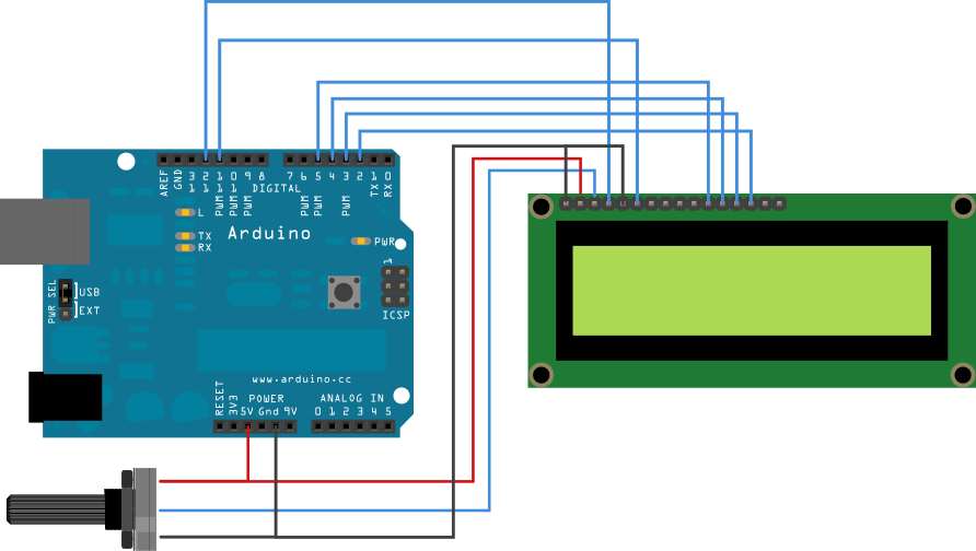
I use this circuit from this link

Code was
// include the library code:
#include <LiquidCrystal.h>
// initialize the library with the numbers of the interface pins
LiquidCrystal lcd(12, 11, 40, 42, 44, 46);
void setup() {
// set up the LCD's number of columns and rows:
lcd.begin(16, 2);
// Print a message to the LCD.
lcd.print("hello, world!");
}
void loop() {
// set the cursor to column 0, line 1
// (note: line 1 is the second row, since counting begins with 0):
lcd.setCursor(0, 1);
// print the number of seconds since reset:
lcd.print(millis()/1000);
}
Show a clear photo or drawing of your wiring as is.
And make it fit to the page, so no huge picture please.
It is not enough to tell that you did it like the tutorial but different (for whatever reason)
Globe still offline.
The first think that I see is:
Supply Voltage: 3V
In the drawing that you send:
1- you have the LCD supply connected to 5V;
2- you have D4...D7 connected to 5...2, and in the code, you have:
LiquidCrystal lcd(12, 11, 40, 42, 44, 46);
OP shows a picture of an Uno, and has told (s)he's using a MEGA.
Telling "I did it -sort of- like that" doesn't help.
Show how it is now.
It's hard to see your own (wiring) errors, so there's nothing wrong with asking someone else to have another look at it.
But that means SHOW IT.
this is wiring

What is the Vcc pin of the MEGA that you are using? 5V, 3.3V or Vin?
I am using 5v
The only thing that I see that could be wrong (according to the data sheet) is the supply voltage that should be 3V.
What do you see? Why you say that the LCD is not working? Did it lights up?
The only thing that I see that could be wrong (according to the data sheet) is the supply voltage that should be 3V.
What do you see? Why you say that the LCD is not working? Did it lights up?
IT SHOW ME SQUARE
For me the problem is the voltage of the display. You have a 3V display connected to 5V supply and 5V data lines. I think that you would be very lucky if you don't kill yet the display.
Try to connect it to 3.3V form your MEGA and see if the behaviour is the same.
Do you have some 3.3V Pro Mini? (I'm asking this because it will be the Arduino with the voltage closer to 3V)
luisilva:
For me the problem is the voltage of the display. You have a 3V display connected to 5V supply and 5V data lines. I think that you would be very lucky if you don't kill yet the display.Try to connect it to 3.3V form your MEGA and see if the behaviour is the same.
Do you have some 3.3V Pro Mini? (I'm asking this because it will be the Arduino with the voltage closer to 3V)
still got square
HazardsMind:
If i'm not mistaken, that pin you labeled as NC in your written schematic, is your contrast pin, which of you look at the schematic you posted here,I use this circuit from this link
http://arduino.cc/en/uploads/Tutorial/LCD_bb.pngit should be connected to a 10k pot.
it didn't work even that way .
IT SHOW ME SQUARE
What exactly does this mean? You will get a single row of 16 rectangles if the initialization is incorrect but you won't see them if pin 3 is left open.
I think it is time for you to disconnect everything and start again.
Here is my generic step by step approach that should work:
(1) If the module has a backlight then get it working properly. This involves only pins 15 and 16 on most LCD modules. Make sure to use a current limiting resistor if there is none on the LCD module.
(2) Get the power and contrast working properly. This involves only pins 1, 2, and 3 on most LCD modules. You should be able to just barely see blocks on one row of a two row display and on two rows of a four row display.
NOTE: The Arduino has not been used yet, except as a possible source for the power needed for the first two steps. Do not try to go any further until this is working. If you don't see the blocks then no amount of program code will help.
(3) Connect the LCD R/W pin (pin 5) to GND.
(4) Connect the six control and data wires between your LCD module and your Arduino.
(5) Upload your sketch and it should work.
Troubleshooting:
If you have a 16x1 display and there are blocks only on the left half of the row in step 2 then use
lcd.begin(8, 2);
in your sketch.
If you still don't get a display then make sure that your wiring matches the numbers in the descriptor (or vice versa).
//LiquidCrystal lcd(RS, E, D4, D5, D6, D7);
LiquidCrystal lcd(7, 8, 9, 10, 11, 12);      // put your pin numbers here
If you get a display but it is garbled or has some other problems then try again with a 'static' sketch, one that displays a simple message on the top row of the display and then stops. All of your code should be in setup() and loop() should be empty between the brackets.
#include <LiquidCrystal.h>

//LiquidCrystal lcd(RS, E, D4, D5, D6, D7);
LiquidCrystal lcd(7, 8, 9, 10, 11, 12);      // put your pin numbers here

void setup()
  {
  lcd.begin(16, 2);                          // put your LCD parameters here
  lcd.print("hello, world!");
  lcd.setCursor(0,1);
  lcd.print("it works!");
  }

void loop()
  {
  }
If you are still having problems then we need to see a photograph of your setup that clearly and unambiguously shows all of the connections between your Arduino and your LCD module. We also need a copy/paste version of the code that you are actually using, not a link to the code that you think you are using.
If you look on page 9/20 in the data sheet which the OP supplied (http://www.farnell.com/datasheets/653655.pdf) it clearly states that pin 3 is NC.
Also the "Electronical Charcteristic" on page 4/20 shows blanks for the difference between the 3v Vdd and the V0, but the section above on absolute maximum ratings shows V0 (power supply lcd) ranging from Vdd-13.5 to Vdd +0.3.
There was a recent posting about another positive transflective lcd which required negative contrast voltage. Perhaps there is a built in charge pump on this one. There is no schematic in the data sheet.
If you look on page 9/20 in the data sheet which the OP supplied (http://www.farnell.com/datasheets/653655.pdf) it clearly states that pin 3 is NC.
Yea, I saw that afterwards. So yes, I was mistaken for thinking it was a normal LCD, that usually has a contrast pin in that very spot.