LCD 2004 (20x4) I2C Library

Noobie here experimenting with an i2c lcd 2004 (20x4). I am hopeful that someone can bump me in the right direction.

I was reading this thread -- IIC/I2C/TWI 2004 20X4 Character LCD Module Display - #16 by system -- and could not follow what library the poster bperrybap was referencing when he mentions "fm's library"?

I have an LCD with an I2c module attached that I purchased from HiLetGo (https://www.amazon.com/gp/aw/d/B01DKETWO2?psc=1&ref=ppx_pop_mob_b_asin_title). I am trying to determine the correct lcd/i2c libraries to use.

Can I use (and should I use) the Extensible hd44780 library (at the following link)?

alternatively, what Liquidcrystal_i2s should I use?

Thanks in advance for any help.

Yes, by all means, use the hd44780 library. It is the best available right now. It is far superior to any of the LiquidCrystal_I2C libraries (like fm's LiquidCrystal library).

Install the hd44780 library. The library is available in the Library Manager. Go to Library Manager (in the IDE menus, Sketch, Include Libraries, Manage Libraries) and in the Topics dropdown choose Display and in the Filter your search box enter hd44780. Select and install the hd44780 library by Bill Perry.

The class that you want to use is the hd44780_I2Cexp class. There are examples to show how to use the library. The nice thing about the hd44780 library is that it will autodetect the I2C address and the I2C backpack to LCD pin mapping. The other libraries will not.

In the examples, there is a diagnostic sketch that will help us to help you if you still have trouble with the display. Run the diagnostic sketch and post the results. And @bperrybap is a regular visitor to this forum and can answer any questions that the rest of us cannot.

Thank you for quick reply. I am away from my PC, but will do as you suggest as soon as I can and post results of diagnostic test.

When you first connect the LCD you may need to adjust the contrast pot so that the display will show up.

With just power (no data) to the display you should see 2 lines of blocks. Adjust the contrast till the blocks just show up.

lcd 2004 blocks

If, after you send data only the blocks are still there, you may have too much contrast and the pot will need adjusting again. Then set the contrast to where the data show up well.

Interesting. Earlier today I wired up the lcd module to my uno and complied and uploaded some code and the LCD displayed the 4 rows of blocks (like your photo, but no lines were skipped-- I had 4 rows of blocks).

EDIT: I will post code that I uploaded when I am back in front of my PC.

EDIT2: Now that I think about it, the 4 rows of blocks may have been displayed on my lcd before (and after) I uploaded code.

The photo was showing what an unitialized 20x4 display should look like when the contrast is properly set.

What you describe indicates too much contrast. You need to adjust the pot.
When you adjust the pot, the pixels will go from all off to all on regardless of what is supposed to be on the display.
i.e. one extreme will force the pixels off, the other forces all the pixels on.
The proper adjustment is somewhere between the two extremes.

--- bill

This is the code that I complied and uploaded to my arduino this morning:

#include <Wire.h>
#include <hd44780.h>                       // main hd44780 header
#include <hd44780ioClass/hd44780_I2Cexp.h> // i2c expander i/o class header

hd44780_I2Cexp lcd; // declare lcd object: auto locate & config exapander chip

// LCD geometry
const int LCD_COLS = 16;
const int LCD_ROWS = 4;

void setup()
{
  lcd.begin(LCD_COLS, LCD_ROWS);
  // Print a message to the LCD.
  lcd.backlight();
  lcd.setCursor(3, 0);
  lcd.print("Hello, world!");
  lcd.setCursor(0, 1);
  lcd.print("It Works!"); 
}

void loop() {}

And it does work?

No :frowning:

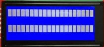
I do see the 2 lines of boxes before loading datre . After uploading program, I still see 2 rows of boxes (i.e. no change).

When I run the diagnostic, the serial monitor printout is as follows.


Serial Initialized


I2CexpDiag - i2c LCD i/o expander backpack diagnostic tool


hd44780 lib version: 1.3.2


Reported Arduino Revision: 1.6.7

CPU ARCH: AVR - F_CPU: 16000000


SDA digital pin: 18 A4

SCL digital pin: 19 A5


Checking for required external I2C pull-up on SDA - YES

Checking for required external I2C pull-up on SCL - YES

Checking for I2C pins shorted together - Not Shorted


Scanning i2c bus for devices..

i2c device found at address 0x27

Total I2C devices found: 1


Scanning i2c bus for all lcd displays (4 max)

LCD at address: 0x27 | config: P01245673H | R/W control: Yes

Total LCD devices found: 1


LCD Display Memory Test

Display: 0

Walking 1s data test: PASSED

Address line test: PASSED

Each working display should have its backlight on

and be displaying its #, address, and config information

If all pixels are on, or no pixels are showing, but backlight is on, try adjusting contrast pot

If backlight is off, wait for next test


Blinking backlight test: to verify BL level autodetection

If backlight is mostly off but

you briefly see "BL Off" on display with backlight on,

then the library autodetected incorrect BL level

and the library cannot autoconfigure the device


Displaying 'uptime' on all displays


I see this both before and after adding data.

const int LCD_COLS = 16;
const int LCD_ROWS = 4;

I thought that you have a 20x 4 display?

Post photos showing your wiring, please.

Are you using a Mega? Do you have SDA of the LCD connected to pin 20 and SCL connected to pin 21?

This tells you the code is not accessing the display at all. Simple as that.

:thinking:

I am embarrassed to say that I had SDA and SCL wired in reverse.

I fixed that, and it works now!!!!!

Thanks to all for help and patience.

I do have a 20x4...the 16 is another mistake.

My uno has an Atmeg328P.

I had SCL and SDA reversed, but now they are in pins 19 and 18, respectivley.

Photo below.

Yeah, I don't normally think of A4 and A5 as pins 18 and 19 even though they really are. I guess I am a bit thick today.

Something doesn't make sense.
It isn't possible for the "It Works!" demo sketch to fail but yet the diagnostic sketch work.
Something changed between running those two sketches.

Easiest thing for SDA and SCL connections on the newer boards is to use the pins labeled SDA and SCL. That way it doesn't matter what digital pin or analog point they are connected to.

--- bill

Yes. I wondered about that. When I uploaded code, I got error if the uno was wired to the lcd module. So, I disconnected to upload and then reconnected. I must have gotten things confused.

The sad thing is that my board was so labeled :smiling_face: