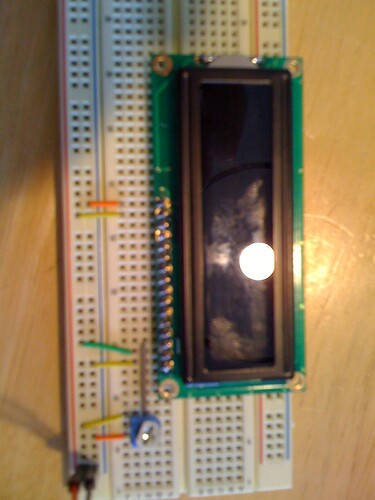
I can not figure out what I am doing wrong. I am trying to hook up a basic LCD on a breadboard. The LCD is clearly getting power but when I adjust the contrast nothing happens. I have attached a photo for reference. I have it connected in the following manner.
Pin 16 Ground
Pin 15 5+
Pin 1 Ground
Pin 2 5+
Pin 3 Pot Wiper 10k
I have also tried a second LCD but that doesn't work either. I have put an LED inline on Pin 3 and turned the pot and the LED brightness changes. Any help is appreciated thanks in advance.
Marc
The LCD is clearly getting power
How do you know this?
but when I adjust the contrast nothing happens.
What do you see?
There are two possibilities that I can think of without more information.
(1) Can you definitely identify pin 1? Your photo is out of focus so I cannot see if there are any board markings. It's possible that pin 1 in near the center of the board rather than the edge. Try disconnecting the +5 volt connections one at a time. When the backlight goes out you have identified pin 16.
(2) Could you possibly have an extended temperature device? In this case you will probably need a slightly negative voltage at pin 3. Try un-grounding the negative end of the potentiometer and connect it instead to the negative end of a battery. Connect the positive battery terminal to ground. This will allow you to get the negative contrast voltage needed to check out this possibility.
Don
This picture hurts my eyes. I managed to trace your connections, assuming pin 1 is on the right side. I don't see obvious problems.
When you supply power, do you see back light turn on? BTW, you need a resistor to limit current on the back light LED.
I want to know if you manage to light the back light or not.
Like floresta said the lcd could be extended temperature model. Can you get a better shot and provide the model number and spec sheet?
Hopefully this picture is a little better. This is the datasheet for the LCD in this picture http://www.sparkfun.com/datasheets/LCD/GDM1602K-Extended.pdf
I also tried using this LCD with no luck
In the picture you can see that the backlight comes on but nothing else happens.
Thanks for looking at this.
Does that second photo accurately depict what you are seeing. I see some light coming out the end of the display but the backlight certainly does not seem correct. I can vaguely see the desired 'boxes' in your display but I see two rows of dim boxes rather than just a single row of bright boxes. Take a look at this tutorial Arduino Tutorial - connecting a parallel LCD and scroll down about half way, just before the section labeled 'Bus Wiring' for a photo of what you should see. (The LCD is upside down in that photo, it's the top row that has the boxes.)
From the datasheets both of your displays seem to require a positive contrast voltage and they both require a current limiting resistor for the backlight which I see you have added. I think 220 ohms is too high since this will limit the backlight current to less than 4 mA. I can't find an LED current rating for the 16x2 but the 20x4 is rated at 240 mA which would mean it needs a much smaller resistor.
Do you think you could find a real camera to use for your pictures? The iPad gives better pictures than the iPhone but neither of their 'cameras' seem to be very good for this type of photo.
Don
Don,
thanks for all the help. As soon as my camera is charged I will post a better picture. I was using the ladyada tutorial when I started this and got to the point of testing the contrast when I realized something was wrong. Is it possible that I burnt out both of the LCD's by not putting a resistor on the backlight pin first?
Thanks again,
Marc
It certainly could have damaged the LED backlight but that in itself has nothing to do with the LCD controller. Unfortunately many of the backlit modules are almost unreadable without the backlight, even if the LCD controller is 'working' properly. You could try disconnecting the backlight power and see if the LCD contrast control seems to have the proper effect even though the display itself will not really be usable. That way you could keep programming while waiting for a replacement display.
Don

