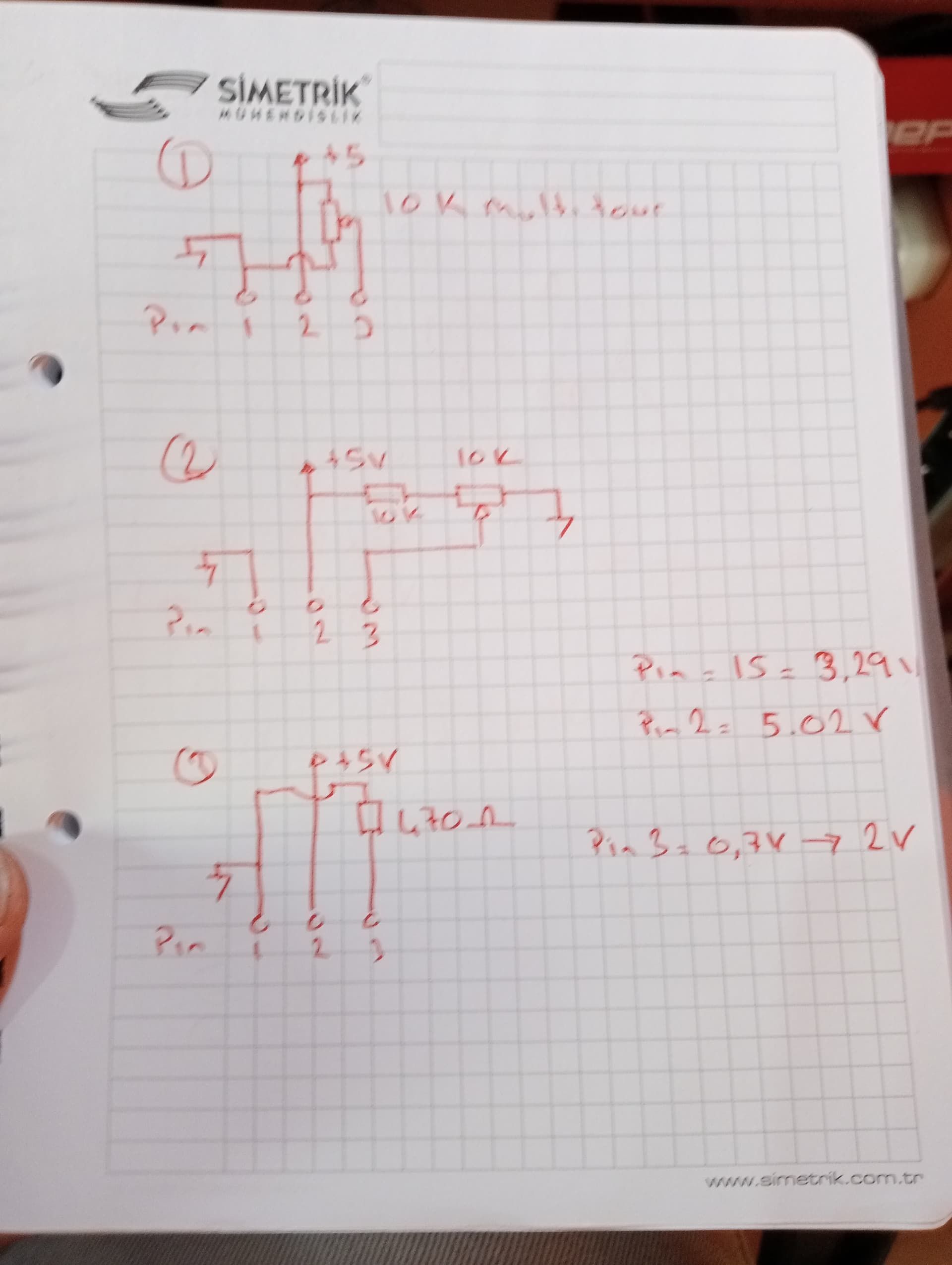
Hello, I made an application with arduino nano and 1602A lcd. When I energize for the first time, everything is normal, after a few minutes, my contrast decreases and nothing can be seen on the LCD. I re-adjust the adjusted resistor connected to Pin3, but after a while the same result again. Meanwhile, the 5v and 3.3v voltages do not change at all. The voltage at pin 3 increases from 0.7 volts to 2.5 volts in amplitude. Tried the 3 connectio
ns shown in the picture, the result is the same. If I connect pin 3 to gnd, the contrast increases a lot. It's been 3 days. I've been struggling, I reinstalled it over and over with 4 different lcds and arduino, the result is the same.
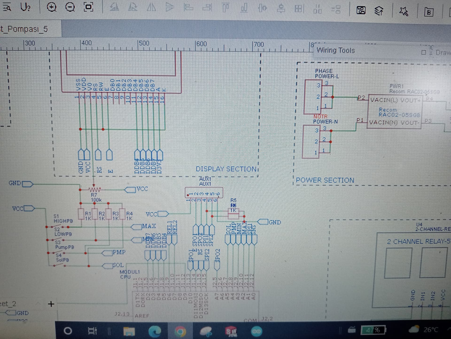
The photo has the original scheme. When the problem came up, I tried the solutions I wrote earlier. The result is the same. When I watch Pin 3 on the oscilloscope, I occasionally see square wave signals,
I would connect the display up on its own and run a sample sketch to see what you get . Then you will know where the issue occurs - it’s hard to know if the problem resides somewhere else in your hardware.
Selam ercankaratas
Keep it simple and stupid and use an I²C interface board for the LCD.
Have a nice day and enjoy programming in C++ and learning.
Errors and omissions excepted.
Well, actually, it isn't. The potentiometer should not be connected to 5 V at all. The schematic labelled 3 shows you a resistor to ground which is correct but you may wish to vary the resistance, so a potentiometer wired as a plain variable resistor is what is required. The appropriate value is actually 1k, but if you only have a 10k resistor, you can make it more usable by connecting both ends to ground (thus halving its effective value) and the wiper to pin 3.
This of course, does not address the fading problem which is due to the power supply collapsing. This is almost certainly due to foolishly attempting to power a UNO or Nano by the "barrel jack" or "Vin". You need to provide a proper regulated 5 V to the "5V" pin as well as the relay module and any other attachments. If using a UNO however, you need to disconnect the "5V" pin while you plug the USB into a PC.
I agree with @jremington] here - if that actually happens, there is a serious wiring fault.
The photo in #1 looks more like a Chip-On-Glass module than the regular 16x2 HD44780 with blobs on fibreglass pcb.
The wiring-diagram / schematic in #3 is a bit suspect. We don't see the "POWER" or "RELAY" sections.
I doubt if the Uno regulator would have a problem with the 2mA consumed by a HD44780 or even the 20mA from some backlights.
But relays, power, active-high switches are very suspicious. More likely to make VCC collapse rather than go "above" 5V.
"Multiple" external power sources seem unwise.
Your power supply seems undersized for your application. With only 2W of power at 5V, this equates to 400mA.
Rough estimate for current consumption of your devices is 50mA (nano) + 150mA (1602 LCD) + 200mA (2-relay module) = 400mA.
I suppose you could connect a 470μF load across 5V to GND (there's a 500μF load limitation). I think this could solve the display fading situation, but a better solution would be to use a separate PS for the relay module. Then as a bonus, you could take advantage of its opto-isolation feature if needed.
Seems possible when measuring from a multimeter ... a scope trace would reveal what's actually happening as the power supply struggles to maintain the load at (or above) its limit.
Thanks for the link. I am intrigued. This is the relevant page for the Sunplus SPLC780D
So I would be VERY interested in the real-life current measurements on your TinPlus TC1602A-01T module.
Typical HD44780, SPLC780, KS0066, ... chips all seem to take microAmps rather than milliAmps.
Just because the datasheet mindlessly copies erroneous information from their Chinese wholesalers (with other errors and Chinglish translations), in no way suggests that this display differs from any other using the HD44780 or its clones.
LED backlight current for this display quoted as 180 mA.
The LCD driver draws - as noted - something in the order of 550 µA. The contrast ladder contributes about 450 µA of that. Wrongly connecting the contrast potentiometer adds a further 500 µA.
i.e. the LCD takes very little current (max 0.8mA)
i.e. the backlight of this particular model takes a LOT of current (180mA)
I have never seen a 16x2 module backlight that draws this much current.
While Paul_B's advice about saving 500uA in the contrast circuit is valid it makes little difference to the overall current. Most goes to the backlight even on modern 16x2.
This is the relevant page #5 from dlloyd's Tinsharp datasheet.
Whereas I can believe the backlight takes 100mA I doubt that the LCD takes 150mA when you look at the LCD controller datasheet.
@dlloyd,
Please could you measure the current taken by your Tinsharp TC1602A-01T i.e. without backlight