Hi,
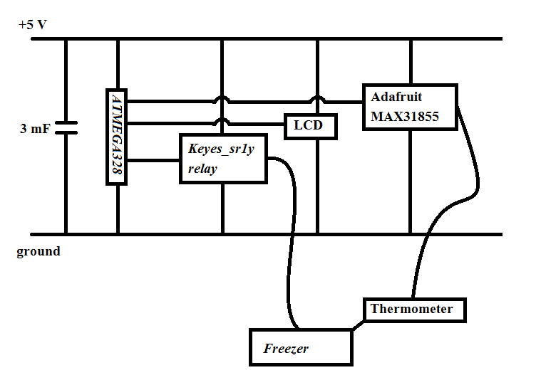
I've built a thermostat that works as I want it, except that the LCD goes bananas sometimes (not always) when the relay switches between on and off (which connects/disconnects a freezer). Thought I'd post it here, to see if anyone else has seen this kind of behaviour (see attachement).
Everything is fed via a single USB-cable. I've tried placing capacitors (3 mF) at the connection of the power supply (USB-cable), but doesnt help (maybe it's a bit more robust now, but still get the behaviour seen in the video from time to time).
When the LCD goes bananas, the thermostat still works as intended, but I can't read the display.
Anyone has any idea what is happening? Could it be the LCD that jumps from 4-bit mode to 8-bit mode? Can that even happen after it has been initialized? (I've no idea how the LCD actually works, I just use the arduino library) I mean after the relay switching, the code seems to work, but somehow the LCD doesn't interpret the data sent to it correctly...
Thankful for any ideas, I'm running out of my own...
Edit: Too big file to attach apparantly, link to the video clip here: