I am using the following components to build an Arduino alarm clock. The breadboard is numbered from 1-30 and from A-J.
Arduino Uno R3
I2C 1602 LCD Display Module
Real Time Clock (RTC) module (DS3231)
3 x Twidec PBS-110-X6C Momentary Push Buttons
Gikfun Passive Electronic Buzzer (EK2146)
3 x 10kΩ resistors
Breadboard
Jumper wires . The three Twidec PBS-110-X6C Momentary Push Buttons are connected to Arduino pin A8, A9 and A10 through the breadboard holes 5A, 10A and 15A. The Buzzer is connected to Arduino pin A11 through breadboard hole 20A. The LCD module is not working. Kindly advise.
Make a hand drawn diagram and photograph it then post.
xfpd
November 4, 2024, 8:05pm
3
kebasita30:
I am using the following
Is this a group of parts you ordered, or a complete kit?
I ordered the parts individually from Amazon.
#include <Wire.h>
#include <LiquidCrystal_I2C.h>

// Define LCD address and pins
const int lcdAddress = 0x27;
const int lcdColumns = 16;
const int lcdRows = 2;

// Define button pins
const int buttonSet = 8;
const int buttonUp = 9;
const int buttonDown = 10;

// Define buzzer pin
const int buzzer = 11;

// Initialize LCD
LiquidCrystal_I2C lcd(lcdAddress, lcdColumns, lcdRows);

// Alarm variables
int alarmHour = 0;
int alarmMinute = 0;
bool alarmSet = false;

// Time-keeping variables
unsigned long previousMillis = 0;
int currentHour = 0;
int currentMinute = 0;
int currentSecond = 0;

void setup() {
  // Initialize LCD
  lcd.init();
  lcd.backlight();

  // Initialize buttons as inputs
  pinMode(buttonSet, INPUT);
  pinMode(buttonUp, INPUT);
  pinMode(buttonDown, INPUT);

  // Initialize buzzer as output
  pinMode(buzzer, OUTPUT);

  // Display initial message
  lcd.setCursor(0, 0);
  lcd.print("Alarm Clock");
  lcd.setCursor(0, 1);
  lcd.print("Time: ");
}

void loop() {
  // Read buttons
  int buttonStateSet = digitalRead(buttonSet);
  int buttonStateUp = digitalRead(buttonUp);
  int buttonStateDown = digitalRead(buttonDown);

  // Update time
  unsigned long currentMillis = millis();
  if (currentMillis - previousMillis >= 1000) {
    previousMillis = currentMillis;
    currentSecond++;
    if (currentSecond >= 60) {
      currentSecond = 0;
      currentMinute++;
      if (currentMinute >= 60) {
        currentMinute = 0;
        currentHour++;
        if (currentHour >= 24) {
          currentHour = 0;
        }
      }
    }
  }

  // Set alarm
  if (buttonStateSet == HIGH) {
    alarmSet = true;
    lcd.setCursor(0, 1);
    lcd.print("Alarm Set");
    delay(1000);
  }

  // Increase alarm time
  if (buttonStateUp == HIGH) {
    if (alarmHour < 23) {
      alarmHour++;
    } else {
      alarmHour = 0;
    }
    lcd.setCursor(0, 1);
    lcd.print("Alarm: ");
    lcd.print(alarmHour);
    lcd.print(":");
    lcd.print(alarmMinute);
    delay(200); // Debounce
  }

  // Decrease alarm time
  if (buttonStateDown == HIGH) {
    if (alarmHour > 0) {
      alarmHour--;
    } else {
      alarmHour = 23;
    }
    lcd.setCursor(0, 1);
    lcd.print("Alarm: ");
    lcd.print(alarmHour);
    lcd.print(":");
    lcd.print(alarmMinute);
    delay(200); // Debounce
  }

  // Check if it's alarm time
  if (alarmSet && currentHour == alarmHour && currentMinute == alarmMinute) {
    // Activate buzzer
    digitalWrite(buzzer, HIGH);
    delay(1000);
    digitalWrite(buzzer, LOW);
  }

  // Display current time
  lcd.setCursor(0, 1);
  lcd.print("Time: ");
  lcd.print(currentHour);
  lcd.print(":");
  lcd.print(currentMinute);
  lcd.print(":");
  lcd.print(currentSecond);

  delay(100);
}
xfpd
November 4, 2024, 8:51pm
6
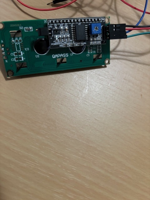
Can you verify your LCD is an I2C LCD? Would you post a picture of the back side of the LCD?
xfpd
November 4, 2024, 8:56pm
8
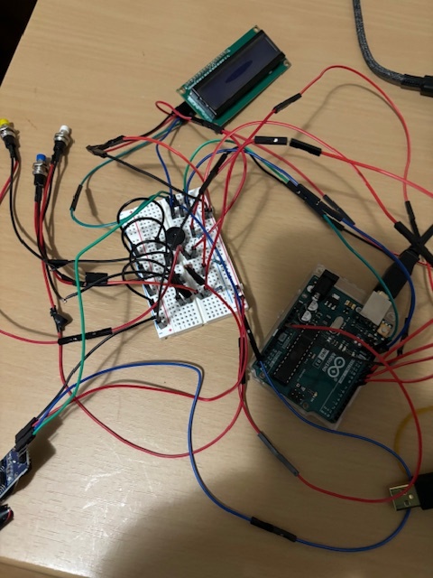
That is good. It is an I2C LCD. Please upload a picture of the wiring so we can see each end of every wire.
F20** (Positive leg of the buzzer) → Arduino Pin A11 .GND rail on the breadboard.
xfpd
November 4, 2024, 10:22pm
13
Unreadable picture. Draw the circuit.
The code does things (but needs work), so the problem is in the wiring.
Hello kebasita30
Welcome to the best Arduino forum ever
Take a view to gain the knowledge.
hth
Three 10K ohms resistors, 5V buzzer , I2C 1602 LCD Display Module and Real Time Clock (RTC) module (DS3231) were used for this alarm clock. The LCD does not work.
xfpd
November 5, 2024, 12:31pm
17
Does your sketch upload?
For the LCD only, look at the pin labels of the LCD... where do the four pins go?
Hi, @kebasita30
kebasita30:
The LCD does not work.
Have you tried one of the example codes that comes with the Library you are using.
Don't try and write a lump of code to try and get everything to work at once.
Write code JUST for each if your peripherals and get it working, before putting them together one at a time.
So start with your display and a library example to prove you have communication with it and control.
Tom..
Have you run an I2C scanner sketch to verify the I2C address of the display?
Yes, I uploaded the sketch. Jumper wires from the VCC and GND pins of the LCD are connected to the breadboard power rail at line 25 (+ and - respectively). There are also GND connections from 5G, 10G and 15G to the (-) rails respectively. The lights on the Arduino and the D3231 are on but the light on the LCD also flickers.