hi everyone.
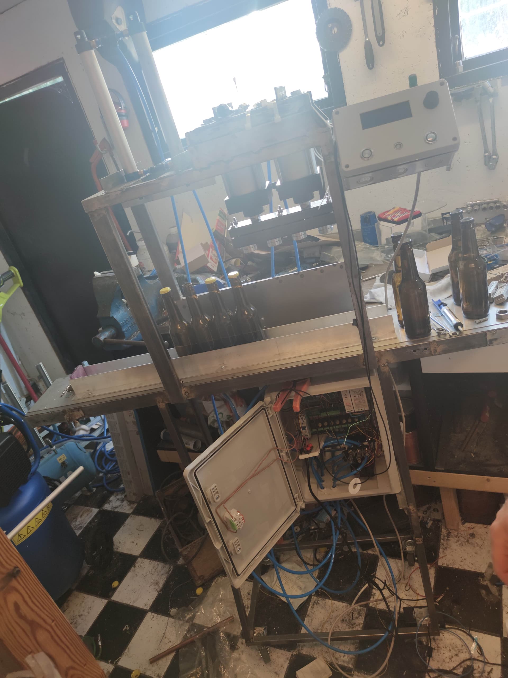
so i think i have read all the threads on the web about LDC problems and trubbleshooting without any luck. I have a 20x4 LCD that's communicates over the I2C bus. the cable that I am using is one wire shielded for the SCL and SDA. they are totaly seperated from each other and from the rest of the cables in the project. the length of the cable is about 80cm. i have tried to use 4.7k omh pullup resistors due to the length of the cable but it did not work. tried to disable the Serialmoniter, but no luck there either. i have also tried to use diffrent power source for the arduino and use power to the LCD from the source, but no luck. i am suspecting that the problem might be in the code and not a hardwear problem. or what do you guys think???
good to now: every thing can work fine for like say 5-6 loops and after that the problem occurs. some thimes the arduino resets itself and somtimes i don't.
#include <Wire.h>

#include <LiquidCrystal_I2C.h>


#include <TimerOne.h>


#ifdef __AVR__
#include <TimerOne.h>
#endif


// Project specific includes.
/**
 *
 */
 //Set the LCD address to 0x27 for a 20 chars and 4 line display
LiquidCrystal_I2C lcd(0x27, 20, 4);


/**
 * InputConfig.h Pin definitions
 */
#define START_BUTTON 8
#define BEER_INLET_SOL_1 5
#define BEER_INLET_SOL_2 6
#define BEER_INLET_SOL_3 7
#define BEER_INLET_SOL_4 9
#define BEER_FILL_SENSOR_1 A0
#define BEER_FILL_SENSOR_2 A1
#define BEER_FILL_SENSOR_3 A4
#define BEER_FILL_SENSOR_4 A3
#define BEER_FILL_SENSOR_POT A2
#define CO2_PURGE_SOL 4
#define FILL_RAIL_SOL 3
#define BEER_BELT_SOL 2
#define CAPER_SOL 10
#define AUTO_BUTTON 11
#define CIP_BUTTON 12
//#pragma once

/**
 * Config.h General Config Options
 */
#define CO2_PURGE_PERIOD 2000
#define MOVE_BEER_BELT_PERIOD 5000
#define FILLER_TUBE_MOVEMENT_DELAY 2000
#define CO2_PURGE_RETRACTION_DELAY 1000
#define CO2_PURGE_RETRACTION_PERIOD 500
#define FILL_SENSORS_TIMER_FREQUENCY 100000 // 100ms This value needs to be defined in microseconds.
#define FILL_SENSORS_TRIGGER 400 // Int between 0 and 1023 used to trigger the fill sensor: operating voltage(5v or 3.3v) / 1024
#define VARIABLE_FILL_SENSOR_TRIGGER true // Use a potentiometer to adjust trigger value
#define CAPER_PERIOD 5000
#define RAISING_FILLER_TUBES_DELAY 2000


/**
 * ***************************************************************************
 * ******************************* VARIABLES *********************************
 * ***************************************************************************
 */
volatile bool fillSensor1Triggered = false;
volatile bool fillSensor2Triggered = false;
volatile bool fillSensor3Triggered = false;
volatile bool fillSensor4Triggered = false;
bool idleMessageDisplayed = false;
enum ProgramState {UNDEF,IDLE,CIP,START,FILLING,STOP};
ProgramState currentState = UNDEF;
int sensorValue;
boolean CONINUOUS_FILLING = false;

/**
 * ***************************************************************************
 * ******************************** FUNCTIONS ********************************
 * ***************************************************************************
 */
void setupPins() {
  // Filler solenoids.
  pinMode(BEER_INLET_SOL_1, OUTPUT);
  pinMode(BEER_INLET_SOL_2, OUTPUT);
  pinMode(BEER_INLET_SOL_3, OUTPUT);
  pinMode(BEER_INLET_SOL_4, OUTPUT);

  // CO2 solenoid.
  pinMode(CO2_PURGE_SOL, OUTPUT);

  // Fill rail solenoid.
  pinMode(FILL_RAIL_SOL, OUTPUT);

  // Beer belt solenoid.
  pinMode(BEER_BELT_SOL, OUTPUT);

  // Fill sensors.
  pinMode(BEER_FILL_SENSOR_1, INPUT);
  pinMode(BEER_FILL_SENSOR_2, INPUT);
  pinMode(BEER_FILL_SENSOR_3, INPUT);
  pinMode(BEER_FILL_SENSOR_4, INPUT);
  pinMode(BEER_FILL_SENSOR_POT, INPUT);

  // Start/Stop button.
  pinMode(START_BUTTON, INPUT);

  // Auto button.
  pinMode (AUTO_BUTTON, INPUT);

  // Caper solenoid.
  pinMode(CAPER_SOL, OUTPUT);
  // CIP button.
  pinMode (CIP_BUTTON, INPUT);
}

/**
 * Setup a non-blocking interrupt timer for checking the fill sensors.
 */
void setupFillSensorsTimer() {
  Timer1.initialize(FILL_SENSORS_TIMER_FREQUENCY);
  Timer1.attachInterrupt(checkFillSensors);
}

/**
 * Feature flags
 */
 //#define CONINUOUS_FILLING // Uncomment this to have the filling process repeat for new batch after the current batch has completed it filling.


/**
 * Check if the fill sensors have been triggered.
 */
void checkFillSensors() {
    if (VARIABLE_FILL_SENSOR_TRIGGER) {
    sensorValue = analogRead(BEER_FILL_SENSOR_POT);
  } else {
    sensorValue = FILL_SENSORS_TRIGGER;
  }
  //Serial.println(sensorValue);
  if (sensorValue < analogRead(BEER_FILL_SENSOR_1)) {
    triggerFullFillSensor1();
  }
  if (sensorValue < analogRead(BEER_FILL_SENSOR_2)) {
    triggerFullFillSensor2();
  }
  if (sensorValue < analogRead(BEER_FILL_SENSOR_3)) {
    triggerFullFillSensor3();
  }
  if (sensorValue < analogRead(BEER_FILL_SENSOR_4)) {
    triggerFullFillSensor4();
  }
}

/**
 * Fired when fill sensor 1 is triggered as full.
 */
void triggerFullFillSensor1() {
  if (!fillSensor1Triggered && hasProgramState(FILLING)) {
    closeBeerFillerTube(BEER_INLET_SOL_1);
    fillSensor1Triggered = true;
    //Serial.println("Filler tube 1 closed");
  }
}

/**
 * Fired when fill sensor 1 is triggered as full.
 */
void triggerFullFillSensor2() {
  if (!fillSensor2Triggered && hasProgramState(FILLING)) {
    closeBeerFillerTube(BEER_INLET_SOL_2);
    fillSensor2Triggered = true;
    //Serial.println("Filler tube 2 closed");
  }
}

/**
 * Fired when fill sensor 1 is triggered as full.
 */
void triggerFullFillSensor3() {
  if (!fillSensor3Triggered && hasProgramState(FILLING)) {
    closeBeerFillerTube(BEER_INLET_SOL_3);
    fillSensor3Triggered = true;
    //Serial.println("Filler tube 3 closed");
  }
}

/**
 * Fired when fill sensor 1 is triggered as full.
 */
void triggerFullFillSensor4() {
  if (!fillSensor4Triggered && hasProgramState(FILLING)) {
    closeBeerFillerTube(BEER_INLET_SOL_4);
    fillSensor4Triggered = true;
    //Serial.println("Filler tube 4 closed");
  }
}


/**
 * Return whether all fill sensors have been triggered or not.
 */
bool allFillSensorsTriggered() {
  return fillSensor1Triggered && fillSensor2Triggered && fillSensor3Triggered && fillSensor4Triggered;
}

void resetFillSensorTriggers() {
  fillSensor1Triggered = fillSensor2Triggered = fillSensor3Triggered = fillSensor4Triggered = false;
}

/**
 * Open a single beer filler solenoid.
 */
void openBeerFillerTube(int fillerTubePin) {
  digitalWrite(fillerTubePin, HIGH);
}

/**
 * Close a single beer filler solenoid.
 */
void closeBeerFillerTube(int fillerTubePin) {
  digitalWrite(fillerTubePin, LOW);
}

/**
 * Open all beer filler solenoids.
 */
void openAllBeerFillerTubes() {
  //Serial.println("Opening all beer filler tubes");
  lcd.setCursor(0,1);
  lcd.print("Opening all ");
  lcd.setCursor(0,2);
  lcd.print ("beer filler tubes");
  digitalWrite(BEER_INLET_SOL_1, HIGH);
  digitalWrite(BEER_INLET_SOL_2, HIGH);
  digitalWrite(BEER_INLET_SOL_3, HIGH);
  digitalWrite(BEER_INLET_SOL_4, HIGH);
  delay (3000);
  lcd.clear();

}

/**
 * Close all beer filler solenoids.
 */
void closeAllBeerFillerTubes() {
  //Serial.println("Closing all beer filler tubes");
  lcd.setCursor(0,1);
  lcd.print ("Closing all beer filler tubes");
  digitalWrite(BEER_INLET_SOL_1, LOW);
  digitalWrite(BEER_INLET_SOL_2, LOW);
  digitalWrite(BEER_INLET_SOL_3, LOW);
  digitalWrite(BEER_INLET_SOL_4, LOW);
  lcd.clear();
}
/**
 * CIP Program
 */
void cipprogram(){
  lcd.setCursor(0,1);
  lcd.print("CIP in progress     ");
  digitalWrite (FILL_RAIL_SOL, HIGH);
  digitalWrite(BEER_INLET_SOL_1, HIGH);
  digitalWrite(BEER_INLET_SOL_2, HIGH);
  digitalWrite(BEER_INLET_SOL_3, HIGH);
  digitalWrite(BEER_INLET_SOL_4, HIGH);
  delay (6000);
  digitalWrite (FILL_RAIL_SOL, LOW);
  digitalWrite(BEER_INLET_SOL_1, LOW);
  digitalWrite(BEER_INLET_SOL_2, LOW);
  digitalWrite(BEER_INLET_SOL_3, LOW);
  digitalWrite(BEER_INLET_SOL_4, LOW);
  digitalWrite(CO2_PURGE_SOL, HIGH);
  delay (1000);
  digitalWrite(CO2_PURGE_SOL, LOW);
  lcd.clear();
  changeProgramState(IDLE);
}

/**
 * Open the CO2 purge solenoid, wait a while and then close it again.
 */
void purgeCO2( bool retract = false ) {
  //Serial.println("Purging CO2");
  lcd.setCursor(0,1);
  lcd.print ("Purging CO2");
  digitalWrite(CO2_PURGE_SOL, HIGH);
  if(!retract) {
    delay(CO2_PURGE_PERIOD);
  } else {
    delay(CO2_PURGE_RETRACTION_PERIOD);
  }
  digitalWrite(CO2_PURGE_SOL, LOW);
  lcd.clear();
}

/**
 * Raise the fillter tubes out of the bottles.
 */
void raiseFillerTubes() {
  //Serial.println("Raising filler tubes");
  lcd.setCursor(0,1);
  lcd.print ("Raising filler tubes");
  delay(RAISING_FILLER_TUBES_DELAY);
  digitalWrite(FILL_RAIL_SOL, LOW);
  delay(CO2_PURGE_RETRACTION_DELAY); // We use CO2_PURGE_RETRACTION_DELAY here as we want to start purging with CO2 as the fill rail raises.
  lcd.clear();
}

/**
 * Lower the filler tubes into the bottles.
 */
void lowerFillerTubes() {
  //Serial.println("Lowering filler tubes");
  lcd.setCursor(0,1);
  lcd.print ("Lowering filler tube");
  digitalWrite(FILL_RAIL_SOL, HIGH);
  delay(FILLER_TUBE_MOVEMENT_DELAY);
  lcd.clear();
}

/**
 * Move the beer belt, wait a while and then stop it again.
 */
void moveBeerBelt() {
  //Serial.println( "Moving beer belt" );
  lcd.setCursor(0,1);
  lcd.print ( "Moving beer belt" );
  digitalWrite(BEER_BELT_SOL, HIGH);
  delay(MOVE_BEER_BELT_PERIOD);
  digitalWrite(BEER_BELT_SOL, LOW);
  lcd.clear();
}

/**
 * Code to run when we are in the IDLE ProgramState
 */
void idleState() {
  if (!idleMessageDisplayed) {
    //Serial.println("Press Start Button to proceed");
    lcd.setCursor(5,1);
    lcd.print("Press Start ");
    idleMessageDisplayed = true;

  }
  readStartButton();
}

/**
 * Code to run when we are in the START ProgramState
 */
 void moveCaper() {
 //Serial.println( "Caping");
 lcd.setCursor(0,1);
 lcd.print( "Capping");
 digitalWrite(CAPER_SOL, HIGH);
 delay(CAPER_PERIOD);
 digitalWrite(CAPER_SOL, LOW);
 lcd.clear();
 }

 /**
  * Code to run when we are in CIP programState
  */
void cipState(){
  cipprogram();
}
/**
 * Code to run when we are in the START ProgramState.
 */
void startState() {
  moveBeerBelt();
  moveCaper();
  lowerFillerTubes();
  purgeCO2();
  openAllBeerFillerTubes();
  changeProgramState(FILLING);
}

/**
 * Code to run when we are in the FILLING ProgramState.
 */
void fillingState() {
  // Check if we are done filling.
  if(allFillSensorsTriggered()){
    lcd.setCursor(0,2);
    lcd.print("Filling Complete");
    raiseFillerTubes();
    purgeCO2(true);
    resetFillSensorTriggers();
    readAutoButton();
    // If done filling, check if we want to do continuous filling or go back to the UNDEF state.
    if (CONINUOUS_FILLING==true){
      changeProgramState(START);
    }else{
      changeProgramState(IDLE);
  }
}
}
/**
 * Code to run when we are in the STOP ProgramState.
 */
void stopState() {
  // Reset the sensors and change ProgramState to UNDEF.
  resetUnit();
  changeProgramState(IDLE);
}

/**
 * Read the start button.
 */
void readStartButton() {
  if(
    HIGH==digitalRead(START_BUTTON)
    && hasProgramState(IDLE)
  ) {
    //Serial.println("Start Button Pressed");
    changeProgramState(START);
  }
}

/**
 * Read the stop button.
 */
void readStopButton() {
  if(
    HIGH==digitalRead(START_BUTTON)
    && !hasProgramState(IDLE)
    && !hasProgramState(START)
  ) {
    //Serial.println("Stop Button Pressed");
    lcd.print ("Stop Button Pressed");
    changeProgramState(STOP);
  }
}
/**
 * Read the auto button.
 */
void readAutoButton(){
  if(
    HIGH==digitalRead(AUTO_BUTTON)
    && !hasProgramState(IDLE)
  ) {
    //Serial.println("Auto Mode active");
    lcd.setCursor(0,3);
    lcd.print ("Auto Mode active");
    CONINUOUS_FILLING = true;
  }
  else if (
    LOW==digitalRead(AUTO_BUTTON)
  ) {
    CONINUOUS_FILLING = false;
  }

}

/**
 * Read the cip button.
 */
 void readCipButton() {
  if(
    HIGH==digitalRead(CIP_BUTTON)
    && hasProgramState(IDLE)
  ) {
    //Serial.println("CIP in progress");
    changeProgramState(CIP);
  }
}
/**
 * Reset the unit,
 */
void resetUnit() {
  //Serial.println("Reseting unit");
  closeAllBeerFillerTubes();
  digitalWrite(BEER_BELT_SOL, LOW);
  raiseFillerTubes();
  digitalWrite(CO2_PURGE_SOL, LOW);
  //Serial.println("Done resetting unit");
  changeProgramState(IDLE);
}

/**
 * Change the ProgramState
 */
void changeProgramState(ProgramState state) {
  // Reset the bool to avoid the IDLE state message to repeat continiously.
  if (IDLE == state){
    idleMessageDisplayed = false;
  }
  currentState = state;
  //Serial.print("Program state changed: ");
  //Serial.println(currentState);
}

/**
 * Check if the currentState matches the passed state.
 */
bool hasProgramState(ProgramState state) {
  if(state == currentState) {
    return true;
  }
  return false;
}

/**
 * Code in this function must always run, avoid delays in here.
 */
void alwaysRun() {
  readStopButton();
  readAutoButton();
  readCipButton();
}

/**
 * ***************************************************************************
 * ***************************** MAIN FUNCTIONS ******************************
 * ***************************************************************************
 */

/**
 * Main setup routine.
 */
void setup() {
  //Serial.begin(115200);//Serial.begin(9600);
  setupPins();
  setupFillSensorsTimer();
  resetUnit();
  Wire.setClock(1000);
  lcd.begin(); // initialize the LCD

}

/**
 * The main program loop, where all the magic comes togetger.
 */
void loop() {
  lcd.setCursor(0,0);
  lcd.print ("Trigger Value")+(sensorValue);
  lcd.setCursor(14,0);
  lcd.print (sensorValue);
  delay(500);
  switch(currentState) {
    case IDLE:
      idleState();
      break;
    case CIP:
      cipState();
      break;
    case START:
      startState();
      break;
    case FILLING:
      fillingState();
      break;
    case STOP:
      stopState();
      break;
  }
  alwaysRun();
}