LED control lights for a slide door status

Dear,
I'm a beginner in the Arduino world, and can't solve a particular issue on my own.
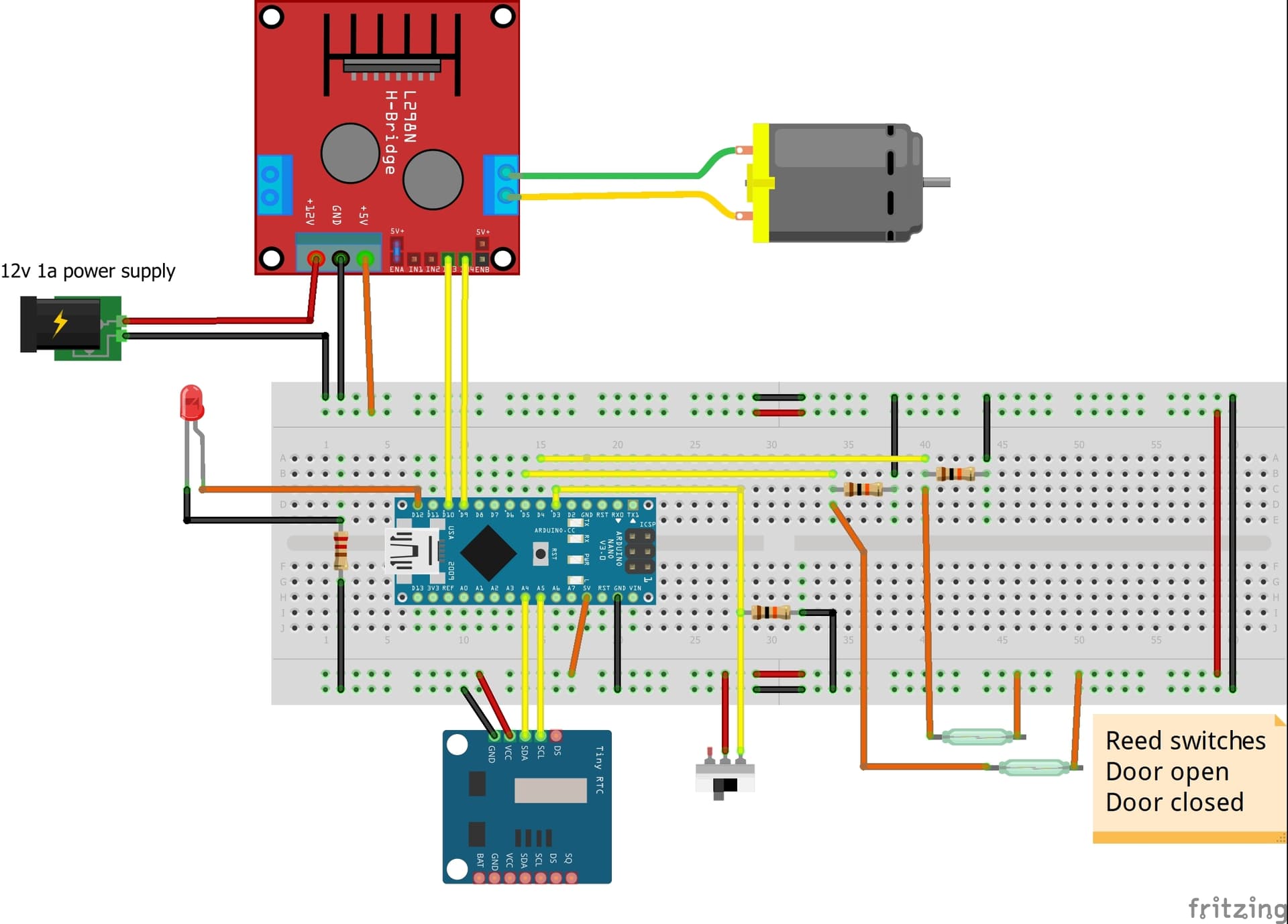
I have a 12V geared motor that operates a slide door. On the door i have 2 microswithes that stops the motor when at the end of the travel and activates a door LED light to indicate the state.

I've used a GREEN LED to indicate that the door is CLOSED and a RED LED to indicate it is OPEN.
I have integrated another LED, which should come on when the door is neither full open or full closed. So, this AMBER led is indicating a TRANSIT situation.

Now, i've been testing around with several IF, Else and IF statements, but i never get it to work like i wish. Whenever the door is in transit, both the GREEN and RED led's should be OFF and the AMBER on. Once at eiher side end-of travel, the AMBER Led should go out, and either the FULL OPEN RED led or the FULL CLOSED GREEN Led should come on.....

My actual code looks like this:

#include <math.h>
#include <Dusk2Dawn.h>
#include <EEPROM.h>
#include <Wire.h>
#include <RTClib.h>

//Define what pins are used
const int doorUpSensorPin = 4;        // reedswitch door open
const int doorDownSensorPin = 5;      // reedswitch door down
const int doorDownMotorPin = 10;      // wind motor down
const int DoorUpMotorPin = 9;         // wind motor up
const int builtInLEDRED = 12;            // LED indicating door closed (microswitch on pin 5)
const int builtInLEDGREEN = 8;        // LED indicating door OPEN ( microswitch on pin 4)
const int transitledAmber = 7;        // LED indicating door in TRANSIT ( neither of the microswitches active)
const byte CloseDoorManual = 3;       // Close door by hand

int buttonstateclose = 0;
int currentMins;
int sunrise;
int sunset;
DateTime now;

//Are We Debugging?
const bool debug = true;
//Do we need to set/adjust RTC?
const bool setRTC = true;

//Define RTC
RTC_DS1307 rtc;

//define the location / timezone for dusk2dawn (this is yourcity, countrycode 2 digit)
// change yourcity an fill in coordinates and timezone
Dusk2Dawn Kapellen(51.31483014538207, 4.458376022992936,+1); 

// the setup function runs once when you press reset or power the board
void setup() {
  
  //Set the mode the pins will operate in.
    pinMode(DoorUpMotorPin, OUTPUT);
    pinMode(doorDownMotorPin, OUTPUT);
    pinMode(CloseDoorManual, INPUT); 

  
  //Set Serial for Debugging
  if (debug) {
    Serial.begin(9600);

    if (!rtc.begin()) {
    Serial.println("Couldn't find RTC");
    while (1);
    }
    
  rtc.begin();
  //   //Lets just set the date/time when setRTC = true.
  if (setRTC)
  {
   //write PC date and time while uploading and when setRTC = true
   rtc.adjust(DateTime(F(__DATE__), F(__TIME__)));

   //uncomment line 71 to write date and time manually into RTC when line 38 setRTC = true. For testing sunset/sunrise
    //rtc.adjust(DateTime(2020, 7, 23, 7, 9, 20));       
  }
}
 
  
  //switches setup
  pinMode(doorUpSensorPin, INPUT);
  pinMode(doorDownSensorPin, INPUT);
  pinMode(builtInLEDRED, OUTPUT);
  pinMode(builtInLEDGREEN, OUTPUT);
  pinMode(transitledAmber,OUTPUT);
    
  Serial.println("FinishedSetup");
  if (digitalRead(doorUpSensorPin) == HIGH) 
  {
   Serial.println("Door is open");
   }

   if (digitalRead(doorDownSensorPin) == HIGH)
   {
    Serial.println("Door is closed");
   }
   delay(3000);
}

// the loop function runs over and over again until power down or reset
void loop() {
  delay(2000);
  if (debug){
    Serial.println();
    Serial.println("SERVO LOOP");
  }
  //Get the Date/Time from the RTC
  now = rtc.now();
  //Get Sunrise/Sunset for the current year/month/day as INT's that equate to minutes from midnight that he sunrise/sunset will occur (THE TRUE is passing in Daylight Savings Time!)
  sunrise = Kapellen.sunrise(now.year(), now.month(), now.day(), true);
  sunset = Kapellen.sunset(now.year(), now.month(), now.day(), true);
  if (debug) {
    Serial.println();
    Serial.print(now.year());
    Serial.print('/');
    Serial.print(now.month());
    Serial.print('/');
    Serial.print(now.day());
    Serial.print(" - ");
    Serial.print(now.hour());
    Serial.print(':');
    Serial.print(now.minute());
    Serial.print(':');
    Serial.print(now.second());
  }


    buttonstateclose = digitalRead(CloseDoorManual);
    if(buttonstateclose == HIGH){
      ManualClose();
    }

  
  //Lets get add the "now" Minutes and "now" hours*60 to see how many minutes from midnight we are
  currentMins = ((now.hour()) * 60) + (now.minute());
  Serial.println(currentMins);

  //lets start comparisons, if the door should be up....
  //delay of 30 minutes after sunset time to make sure all chickens are inside before closing the door. 
  if ((sunrise - 45 < currentMins && currentMins < sunset + 20) && ( buttonstateclose != HIGH))
  {
    Serial.println("Door state --  must be up");
    while ( digitalRead(doorUpSensorPin) == LOW )
    raiseDoor();
    }

  else
  {
    Serial.println("Door state -- must be down");
    while ( digitalRead(doorDownSensorPin) == LOW )
    lowerDoor();
   }


  int DoorUp = digitalRead(doorUpSensorPin);
  int DoorDown = digitalRead(doorDownSensorPin);
  /* This is just temporary switch debug code*/
  if (DoorUp == HIGH)
  {
    Serial.println("Door Full OPEN");
    digitalWrite(builtInLEDRED, LOW);
    digitalWrite(builtInLEDGREEN, HIGH);
    digitalWrite(transitledAmber, LOW);
    stopDoor();
    
  }

 if (DoorDown == HIGH)
  { 
    Serial.println("Door Full CLOSED");
    digitalWrite(builtInLEDRED, HIGH);
    digitalWrite(builtInLEDGREEN, LOW);
    digitalWrite(transitledAmber, LOW);
    stopDoor();

  }

if (DoorDown == LOW && Doorup == LOW)
  {
    Serial.println("Door TRANSIT");
    digitalWrite(builtInLEDRED, LOW);
    digitalWrite(builtInLEDGREEN, LOW);
    digitalWrite(transitledAmber, HIGH);
    stopDoor();
  }
}
 

//Wind the Door Up
void raiseDoor() {
  digitalWrite(DoorUpMotorPin, HIGH);
  digitalWrite(doorDownMotorPin, LOW);
  if (debug) {
    Serial.println("Door moving UP");
    stopDoor(); 
  }
}

//Wind The Door Down
void lowerDoor() {
  digitalWrite(doorDownMotorPin, HIGH);
  digitalWrite(DoorUpMotorPin, LOW);
  if (debug) {
    Serial.println("Door moving DOWN");
    stopDoor(); 
  }
}

//Stop the Door
void stopDoor() {
  digitalWrite(DoorUpMotorPin, LOW);
  digitalWrite(doorDownMotorPin, LOW);
  if (debug) {
    Serial.println("Door Stop");
  }
}

//Close door manual
void ManualClose() { 
  digitalWrite(doorDownMotorPin, HIGH);
  digitalWrite(DoorUpMotorPin, LOW);
  if (debug) {
    Serial.println("Door Closing Manual");
  while ( digitalRead(doorDownSensorPin) == LOW)
    digitalWrite(transitledAmber, HIGH);
    stopDoor(); 
  }
 }

What do i need to do, to get it work???
ps, there's also a manual override switch, that allows me to CLOSE the door manually....

Thanks in advance for the tips and help.

Krgds
Kim

Great explanation of what the things are supposed to do. What does the thing do instead of what it's supposed to do?

Chicken coop door control? I've recently got a chicken coop and am looking to do a chicken coop door control project in the very near future.

Why not name them DoorOpenedLED, DoorClosedLED?

what happens if door up and door down sensor are both LOW?

On another chicken coop project the fellow put in a buzzer that sounded off in a pattern to warn the chickens door opening, time to come into the coop, and door closing. Chickens learned what to do with each sound with a little help from the coop's owner.

Thanks for the reply. The names are not that important. It's the state condition of the microswitches that drive the LED's and so i'm looking for the code to program

"when DOOR CLOSED switch is not activated AND DOOR OPEN switch is not activated ... THEN the amber led will be HIGH."
don't know how the code needs to be written to get me this condition.

it does everything i want: It opens and closes when the dusk and dawn time is there. The microswitches work fine for the GREEN and the RED led, but not for the AMBER transit LED

Hi,
Have you got some simple code to get your LED logic to work as you want it?

That's a lot of complex code for a beginner.
What are all the libraries for.

Get some simple code to work the LED problem.
When you have it solved, integrate it into your main code.

Tom.. :smiley: :+1: :coffee: :australia:

Hey Tom, as beginner, i indeed got the code from a friend. The code is indeed for a chicken coop door, so i just used it and adapted it here and there. So far it works fine, just not for my AMBER transit led....

Why do you want to stop the door in transit? So that above if{} statement does not work, correct?

did you try

Serial.print( "DoorDown  " );
Serial.print( DoorDown  );
Serial.print( " Doorup " );
Serial.print( Doorup );
Serial.println();
if (DoorDown == LOW && Doorup == LOW)
  {
    Serial.println("Door TRANSIT");
    digitalWrite(builtInLEDRED, LOW);
    digitalWrite(builtInLEDGREEN, LOW);
    digitalWrite(transitledAmber, HIGH);
    stopDoor();
  }

to see the deets of why the if statement is not being done up?

Also, should the lighting up of the in transit LED stop the door?

Are the GPIO inputs of door up and down drawn low when not high or are they left floating?

see pulldown.

Good point... I didn't saw the DOOR STOP line when the transit light is activated. Will try your code suggest.....

For this rule i think it must be differently addressed :

if (DoorDown == LOW && Doorup == LOW)

i'll think it must be :

if (DoorDown == LOW && ( DoorUp == LOW))

So within extra ( )

I'm into grouping.

I'd do:

if ( (DoorDown == LOW) && (Doorup == LOW) )

.

What did the serial.prints show?

Also, for 2 seconds, delay(2000); the program will not know the sate of the door but may be driving a motor.

The extra parentheses remove the doubt you have, but you should do it like @Idahowalker shows.

But they are unnecessary here. See

https://en.cppreference.com/w/c/language/operator_precedence

or your favorite learning source on the topic "operator precedence".

So that part isn't your problem.

a7

So to give you a full report on how it's working now: with this full code :

#include <math.h>
#include <Dusk2Dawn.h>
#include <EEPROM.h>
#include <Wire.h>
#include <RTClib.h>

//Define what pins are used
const int doorUpSensorPin = 4;        // reedswitch door open
const int doorDownSensorPin = 5;      // reedswitch door down
const int doorDownMotorPin = 10;      // wind motor down
const int DoorUpMotorPin = 9;         // wind motor up
const int builtInLEDRED = 12;            // LED indicating door closed (microswitch on pin 5)
const int builtInLEDGREEN = 8;        // LED indicating door OPEN ( microswitch on pin 4)
const int transitledAmber = 7;        // LED indicating door in TRANSIT ( neither of the microswitches active)
const byte CloseDoorManual = 3;       // Close door by hand

int buttonstateclose = 0;
int currentMins;
int sunrise;
int sunset;
DateTime now;

//Are We Debugging?
const bool debug = true;
//Do we need to set/adjust RTC?
const bool setRTC = true;

//Define RTC
RTC_DS1307 rtc;

//define the location / timezone for dusk2dawn (this is yourcity, countrycode 2 digit)
// change yourcity an fill in coordinates and timezone
Dusk2Dawn Kapellen(51.31483014538207, 4.458376022992936,+1); 

// the setup function runs once when you press reset or power the board
void setup() {
  
  //Set the mode the pins will operate in.
    pinMode(DoorUpMotorPin, OUTPUT);
    pinMode(doorDownMotorPin, OUTPUT);
    pinMode(CloseDoorManual, INPUT); 

  
  //Set Serial for Debugging
  if (debug) {
    Serial.begin(9600);

    if (!rtc.begin()) {
    Serial.println("Couldn't find RTC");
    while (1);
    }
    
  rtc.begin();
  //   //Lets just set the date/time when setRTC = true.
  if (setRTC)
  {
   //write PC date and time while uploading and when setRTC = true
   rtc.adjust(DateTime(F(__DATE__), F(__TIME__)));

   //uncomment line 71 to write date and time manually into RTC when line 38 setRTC = true. For testing sunset/sunrise
    //rtc.adjust(DateTime(2020, 7, 23, 7, 9, 20));       
  }
}
 
  
  //switches setup
  pinMode(doorUpSensorPin, INPUT);
  pinMode(doorDownSensorPin, INPUT);
  pinMode(builtInLEDRED, OUTPUT);
  pinMode(builtInLEDGREEN, OUTPUT);
  pinMode(transitledAmber,OUTPUT);
    
  Serial.println("FinishedSetup");
  if (digitalRead(doorUpSensorPin) == HIGH) 
  {
   Serial.println("Door is open");
   }

   if (digitalRead(doorDownSensorPin) == HIGH)
   {
    Serial.println("Door is closed");
   }
   delay(3000);
}

// the loop function runs over and over again until power down or reset
void loop() {
  delay(2000);
  if (debug){
    Serial.println();
    Serial.println("SERVO LOOP");
  }
  //Get the Date/Time from the RTC
  now = rtc.now();
  //Get Sunrise/Sunset for the current year/month/day as INT's that equate to minutes from midnight that he sunrise/sunset will occur (THE TRUE is passing in Daylight Savings Time!)
  sunrise = Kapellen.sunrise(now.year(), now.month(), now.day(), true);
  sunset = Kapellen.sunset(now.year(), now.month(), now.day(), true);
  if (debug) {
    Serial.println();
    Serial.print(now.year());
    Serial.print('/');
    Serial.print(now.month());
    Serial.print('/');
    Serial.print(now.day());
    Serial.print(" - ");
    Serial.print(now.hour());
    Serial.print(':');
    Serial.print(now.minute());
    Serial.print(':');
    Serial.print(now.second());
  }


    buttonstateclose = digitalRead(CloseDoorManual);
    if(buttonstateclose == HIGH){
      ManualClose();
    }

  
  //Lets get add the "now" Minutes and "now" hours*60 to see how many minutes from midnight we are
  currentMins = ((now.hour()) * 60) + (now.minute());
  Serial.println(currentMins);

  //lets start comparisons, if the door should be up....
  //delay of 30 minutes after sunset time to make sure all chickens are inside before closing the door. 
  if ((sunrise - 45 < currentMins && currentMins < sunset + 20) && ( buttonstateclose != HIGH))
  {
    Serial.println("Door state --  must be up");
    while ( digitalRead(doorUpSensorPin) == LOW )
    raiseDoor();
    }

  else
  {
    Serial.println("Door state -- must be down");
    while ( digitalRead(doorDownSensorPin) == LOW )
    lowerDoor();
   }


  int DoorUp = digitalRead(doorUpSensorPin);
  int DoorDown = digitalRead(doorDownSensorPin);
  /* This is just temporary switch debug code*/
  if (DoorUp == HIGH)
  {
    Serial.println("Door Full OPEN");
    digitalWrite(builtInLEDRED, LOW);
    digitalWrite(builtInLEDGREEN, HIGH);
    digitalWrite(transitledAmber, LOW);
    stopDoor();
    
  }

 if (DoorDown == HIGH)
  { 
    Serial.println("Door Full CLOSED");
    digitalWrite(builtInLEDRED, HIGH);
    digitalWrite(builtInLEDGREEN, LOW);
    digitalWrite(transitledAmber, LOW);
    stopDoor();

  }

if (DoorDown == LOW && DoorUp == LOW)
  {
    Serial.println("Door TRANSIT");
    digitalWrite(builtInLEDRED, LOW);
    digitalWrite(builtInLEDGREEN, LOW);
    digitalWrite(transitledAmber, HIGH);
    
  }
}
 

//Wind the Door Up
void raiseDoor() {
  digitalWrite(DoorUpMotorPin, HIGH);
  digitalWrite(doorDownMotorPin, LOW);
  if (debug) {
    Serial.println("Door moving UP");
    stopDoor(); 
  }
}

//Wind The Door Down
void lowerDoor() {
  digitalWrite(doorDownMotorPin, HIGH);
  digitalWrite(DoorUpMotorPin, LOW);
  if (debug) {
    Serial.println("Door moving DOWN");
    stopDoor(); 
  }
}

//Stop the Door
void stopDoor() {
  digitalWrite(DoorUpMotorPin, LOW);
  digitalWrite(doorDownMotorPin, LOW);
  if (debug) {
    Serial.println("Door Stop");
  }
}

//Close door manual
void ManualClose() { 
  digitalWrite(doorDownMotorPin, HIGH);
  digitalWrite(DoorUpMotorPin, LOW);
  if (debug) {
    Serial.println("Door Closing Manual");
  while ( digitalRead(doorDownSensorPin) == LOW)
    digitalWrite(transitledAmber, HIGH);
    stopDoor(); 
  }
 }

When power ON : ( 12Volt)
GREEN + RED + AMBER LED's are on, without either one of the door close or door open microswitches activated and motor turning clockwise. Manual door close switch was on, so the motor was turning to close the door.

When i pressed the Door CLOSE microswitch following happens :
** GREEN LED ON
** MOTOR STOPS
** RED LED off
** AMBER LED off

When releasing the microswitch ( so simulating that the door is not fully open then the following happens :
** GREEN LED remains on ( while it should be off since the microswitch states that the door is NOT closed).
** AMBER LED comes ON. (telling me that the door is indeed in transit. So, inbetween full open and full closed). This is indeed correct as long as neither one of the microswitches confirms a Door Close, or a Door Open....

When returning the manual switch to automatic ( so, connecting the motor to the timer circuit)
next happens :

** MOTOR starts turning CCW counterclockwise . Which is normal, given the time of the day. The door must be OPEN for the chickencoop.

** GREEN LED is ON which should be still OFF while the door is not fully open yet. So when the doorUpSensorPin becomes HIGH, only then the LED should turn ON.

**AMBER LED is out ( which is not correct. The LED should turn ON when the doorUpSensorPin is LOW and the doorDownSensorPin is LOW as well.

** RED LED is out, which is normal as the door in motion towards the full open state. ( doorDownSensorPin LOW, means the red led is out.)

ONCE THE DOOR IS FULL OPEN, then the doorUpSensorPin is activated and following happens :

** MOTOR STOPS ( ok )
** RED LED is ON ( which is also ok)
** AMBER LED is off ( which is also ok, as the door is not longer in motion).
** GREEN LED is off ( which is also ok, as the door is not closed, but open).

When i release ( in this state ) the microswitch Door full open ( so simulating that the door is still not fully open), following happens :

** MOTOR start again ( CCW) which is normal, as the circuit attempts to re-close the door at full.
** RED LED is ON which should NOT be on, as the door is NOT fully OPEN.
** GREEN LED is off ( normal as the door is not full closed)
** AMBER LED is off , which in this case, should again be ON, till the micro switch states that the door is full open again....

So, this is what happens now... with the code in this reply

ok, will try this

What printed out for the variable state?

Do you have pulldown resistors?

Do you have resistors on your microswitch inputs?

switch wiring

Yes, the hookup scheme is this.... ( i don't use reed switches but microswitches).

yes, See the scheme below how it is wired. :wink:

What printed out for the variable state?