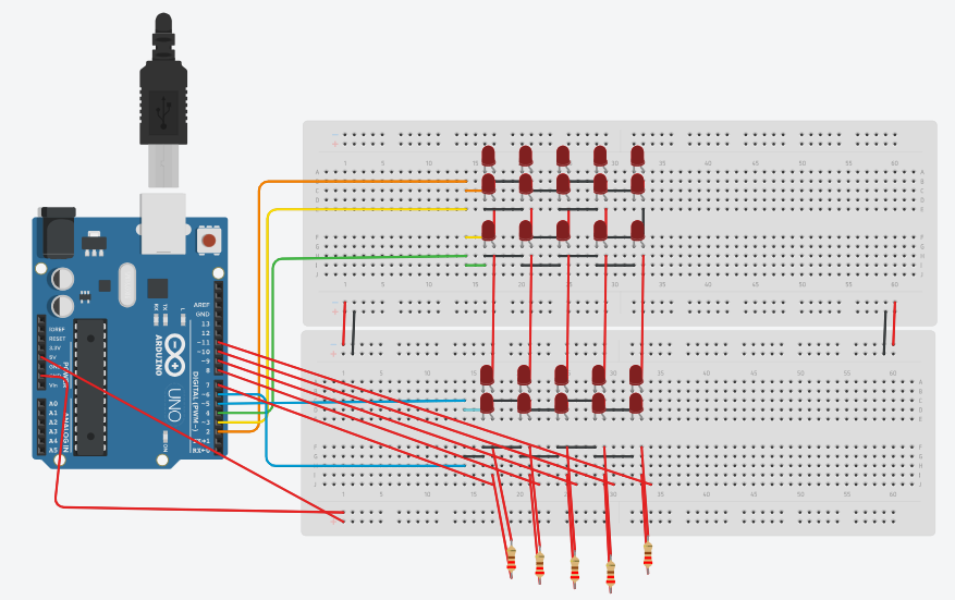
Good evening. I am seeking assistance with this activity. I am uncertain if my wiring is correct because when I run the simulation, some of the LEDs do not turn on. I also attempted to place the wire at the end of each resistor and connect it to pins 7 through 11, but it did not work either.
Yes, your wiring is incorrect.
1 Like
what part is incorrect? can i ask for guidance?
Pins 7 to 11 are not connected to any other components.
The resistors are incorrectly placed and their values are too low. I would recommend 820R
And I think you need a jumper connecting the +V and _V buses at these points red marked.

Also your first 2 rows of LEDs are shorted together.
You could use a MAX7219. Uses fewer pins and needs only one current limit resistor
i tried to adjust my leds below so that my wires are not connected in positive rail of the breadboard and tried to connect the wires below the end of each resistor, but it did not run.
No, they are not needed. The buses are not being used. @ch8 you can remove the wires from the Uno ground pins to the breadboard buses, and the wires between the breadboard buses. None are needed.
1 Like
we are limited only in using arduino uno R3 and breadboard because we will do it in actual
Your description is confusing. Please post the updated/corrected wiring diagram.
1 Like
Tanks... now I need to change my glass to a new. ![]()
![]()
![]()
![]()
I am so sorry, it is already updated
Apology accepted. Please always post updated code or diagrams in a new post.
Your new diagram is different but not closer to being correct. EDIT: I changed my mind. It is further from correct than the previous diagram.
I think maybe you do not understand which sets of holes in the breadboard are connected together and which are not.
I think you will need to add a third breadboard.
1 Like

Thank you. I have attempted the activity again. To be honest, I am confused because it is quite different from what my professor taught.
Are you going to post the updated diagram?
I don't think so. It is more likely that you did not understand. That is why your professor has tasked you to create the circuit, so that he/she can discover if you have understood or not.
Hi! Could you please post the code that you are using? That way, we can examine both your physical setup and your code. Thanks!
1 Like
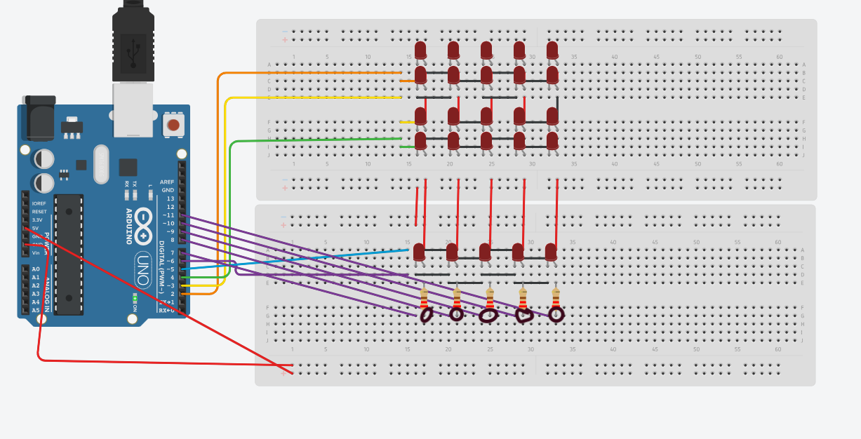
P.S. Your resistors (see circled parts in the diagram) are not connected to anything on one end. Maybe you confused the orientation of the purple wires, which are also not connected to anything. I assume the resistors and the wires are supposed to be connected.
1 Like

I already turn on the 2 rows in 2nd breadboard, but the 3 rows above doesn't turn on. Can you help me? In the right side is my draft code
Code:
const int rows[] = {2, 3, 4, 5, 6};
const int cols[] = {7, 8, 9, 10, 11};
int matrix[5][5] = {
{1, 0, 1, 0, 1},
{0, 1, 0, 1, 0},
{1, 0, 1, 0, 1},
{0, 1, 0, 1, 0},
{1, 0, 1, 0, 1}
};
void setup() {
for (int i = 0; i < 5; i++) {
pinMode(rows[i], OUTPUT);
pinMode(cols[i], OUTPUT);
}
}
void loop() {
for (int row = 0; row < 5; row++) {
digitalWrite(rows[row], HIGH);
for (int col = 0; col < 5; col++) {

  digitalWrite(cols[col], matrix[row][col]);
  delay(1000);


digitalWrite(rows[row], LOW);
}
}
}