Hi to all.. Happy new year.
I didnt know how to summarize my problem in order to add more proper Headline
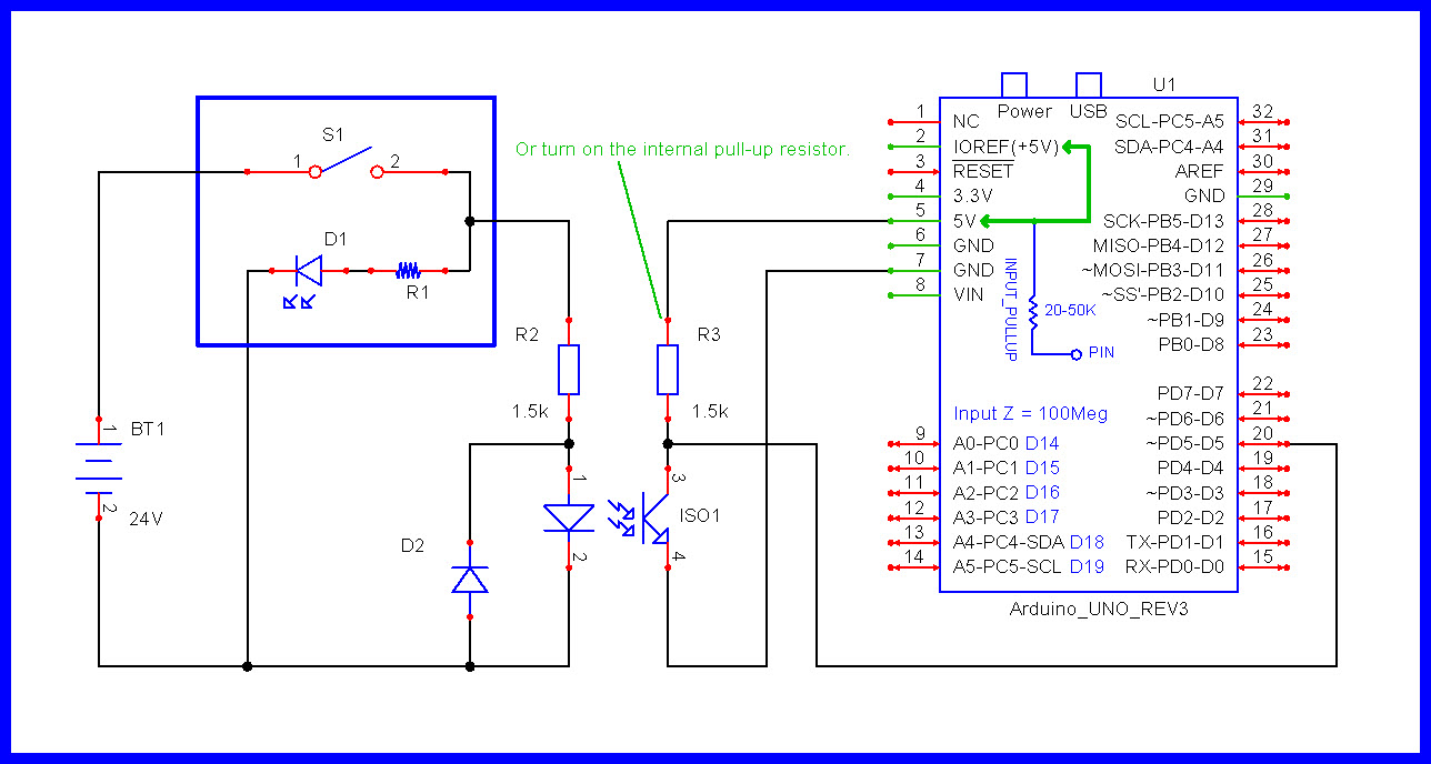
As you can see in my schematic (picture) i am using an 817 optocoupler to read an external button with my arduino.
My buttons have internal led light that goes on when i press them.
My program in Arduino reads the press and store it in a variable and after do what has to do it deletes the variable.
i would like my led in the button to be on from the time i press it until my code execute the function that is assigned with the button press.
i guess the only way is to use an other pin to drive the led until the end of the function.
should i use an other opt-coupler to do that or are other ways?
any suggestions would be welcomed
Ps : ( the value of the resistor in the input of the opt-coupler in my drawing is not right for 24vdc as i want to use.. it is from my previous calculation of 9vdc i was using )
My mistake not placing it.. the second part (the right connection of the opt-coupler is grounded with Arduino ground. most of the times i am using the same 5v source as the one i use to power my Arduino
raschemmel :
if you look better to the drawing you will see that the led in order to work must be powered with 24vdc (the buttons have integrate circuits for the leds to powered with that voltage) so i don't think that Ohm's Law has to do with that i was asking for.
i dont think that is possible to drive that led there direct with Arduino pin (so need to calculate the resistor to connect it).
Hi (thanks for the effort to draw the schematic)
Based on that i want when i press the S1 switch the microcontroller read it and store it in a variable and call one function in the program.
i want until the end of that function the Led that is in the button to be switched on and when the program finishes the function the led goes off.
so i am guessing i will have to use an other IO of the microcontroller to drive the led based in my code.
Two digital pins per button (one to read the switch and the other one to power off/on the led in the switch. ( so if i want to have 3 buttons then i will have to count to use 6 IO )
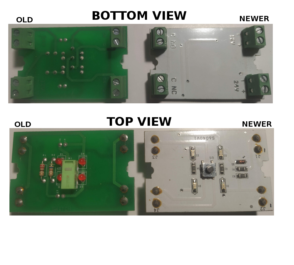
here are some older buttons i had :
Way of connection : I use the two terminals (com, No) for the switch.
In order to have the led power on on press i use a jumper wire from terminal No to - or + side terminal of the led depending what polarity i will use for the common in switch.
i reversed engineering the older one and the schematic is like the last one picture (the newer is almost the same but with smd parts and some new parts as a zener diode for more protection i guess)
LarryD Thanks. So i will have to use an other opt-coupler as i was guessing.
Thanks and for the Drawing, you make my life easier
LarryD : "Redrawn, you can see the 24V battery charging the 12V battery"
The button has two option. to power it with 12v or 24v not both the same time so i guess that is why the old pcbs were made like this... i think that in the newer versions have change that (but i am not sure )
My test project is to Drive an small AC motor with a small VFD
(The arduino will control some Relay modules that will close/open the terminals in the VFD - control it)
The buttons will be far away from the Arduino so 12v or 24v is better . I want to have the internal leds working in order to have optical verification that the command was send and accepted from arduino (with always an emergency stop double switch to cut main supply in the motor and send stop command to arduino)
so i think will be better insulate my arduino pins from the setup in case something connected wrong
To avoid extra cables i thought to make something like that in order to use only 2 cables as (+/-) and one cable per button.(for 1 or 2 buttons it is not so much of deal but if i want to use more than 4 buttons then it helps )
(the values of the resistors are not right i haven't calculate them when i draw the schematic)
i tried that configuration in a breadboard with just one button and seem to work (just the led light when it is driven by Arduino is not so bright as when it takes direct power from the switch but that is not big problem)
DEFINE "SMALL"
If it's actually a 2-wire small AC motor, I don't think it is a VFD. I think it is a simple AC single phase motor control,and if it is a brushless 3-phase motor then it is a simple brushless
motor controller like the type used in RC. The term VFD is reserved for large motor controllers
in the thousands of watts range (ie 38kW Danfoss VFD)(which I used at Tesla to drive a 37kw
Fakuta servo motor)
LarryD : Why i refused to provide it? i post the pictures of the 2 versions of the switch pcbs i had in my hands and also reverse engineering the pcb of the one and post it (the one that you find funny design . There is no more circuits on the switch.
Yes i know that my last schematic has nothing to do with the one in post you kindly offered but i wanted to avoid the one extra cable that was needing in order to work from the switch to the pcb with the optocouplers
raschemmel we are talking about an 3 phase Ac induction asynchronous motor of 1,5 Kw and the VFD is a single phase to 3 phase 2.2Kw