Ello, I was thinking about getting a neopixel led strip, and wrapping it around a cylinder to effectively make a 2D cylinder screen. This cant be an original idea so I wanted to check if anyone has tried this before and how addressing it could work / what library to use in order to translate a 2D pixel function e.g. from a basic shader or code to a 1D spiral mapping.
I guess you would just generate your 2D array then loop through it and fine tune the modulo per average column width, although it wouldnt be ideal without some sort of blending, Im not sure. Maybe theres a library for it or a common used approach?
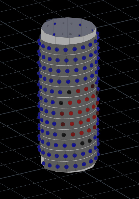
Draw a picture. I imagine a 2D array as a flat screen.
Addressing:
If the "LED strip" is addressable, for example WS2812 or WS2811 or APA106, you would first load a library (a one-line command), then create an object (a one-line command), then use the functions inside the library to make changes in the individual LEDs.
Two popular libraries are Adafruit_Neopixel and FastLED, but you can also use assembly language to create your own functions. The world is your Neopixel.
its a 2D pixel space mapped onto a cylinder, my plan was to work that way, although it could be mapped that way too, sampling the cylinder in 3D space, I thought the 2D approach would maybe be simpler
No. If it has three dimensions (L + W + H), it is 3D - that is what the "3" and the "D" mean. If it has two dimensions, it is 2D. Would you call a model globe 2D? A house? Stick to standards and you won't confuse anyone.
2D panels of WS2812 exist. Curl them around and you have a cylinder. Address them as you would a 2D panel of WS2812.
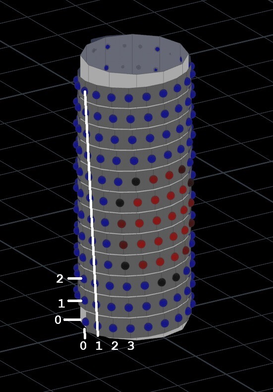
If you want to use "1D" strip of WS2812, count the number of pixels in one circumference and consider each pixel as one "column." Count the number of loops created by the strip, around the cylinder, and consider that value the number of "rows." To find a specific pixel use:
The map is 2D, the object is 3D, I think we are both in agreement. I was just curious if there is a library or an optimal approach for mapping a configuration like this since there isnt a distinct seperation between rows, it may be something involving interpolation, or maybe I am overthinking it. I was just curious if there are examples of how mapping this sort of configuration could be tackled.
thank you for your time, this is the first approach I was thinking of, I was just thinking it might not be ideal since when the row ends it has shifted up by one row, so there will be a diagonal distortion in the coordinate space, which is why I was curious about approaches with blending/mixing in some way, but I think this approach makes sense to start with.
If I were designing this, I would run LED strips lengthwise along the cylinder, so it'd be a simpler matter of dealing with rows and columns of pixels and no diagonals.
You could even connect the ends together to form a zig-zag pattern (one strip goes up, the next goes down, the next goes up, etc.) so that it's still a single strip, and then it's a simple matter of reversing the direction of every other row of pixels, which is still simpler math than dealing with diagonals.
I made a simulation for a user who went through "learning the math" - upside down, alternating rows, backwards - but eventually got to an understanding. Here's the sim, contains the link to the topic.
Horizontal was a no-go, but vertical makes total sense? TFW? Math would then become the totally sensible, altogether same:
// pixel = rowNumber * pixelsPerRow + colNumber; // first row = 0 <- dumb idea
pixel = colNumber * pixelsPerCol + rowNumber; // first col = 0 <- total sense idea
horizontally it seemed weird to deal with the seams and connections, although after taking some more time looking about online I think what you said about using a flexible 2D matrix is probably going to be the most practical solution, since I realised its just as cheap (not sure why I thought a 1d strip would be cheaper) and I wont need to do any cutting / soldering. Thanks for all your advice.
The LED strip in the original idea would have been diagonal, not horizontal. And in most configurations the LEDs wouldn't line up vertically either, so you'd end up with both diagonal "rows" and diagonal "columns".