I have lots of LEDs, various colors, clear, RGB (common cathode just to confuse things), etc. No idea of manufacturer so no data sheet. My Mtester will tell me the VsubF so I know how much V it takes to turn them on. Primarily using Arduino so have 5V to play with, but also play around with 3V, 6V, 9V, etc. Most schematics show a 220 ohm dropping resistor used with a LED @ 5V, but I see other values(180,270,470,1K, etc.) being used as well. Yes I know VsubF and resistor voltage drop must equal less than VSS, but why 220ohm? Also there seems to be no consensus of whether the resistor goes on the anode or cathode side of the LED? So I blindly follow the crowd and put a 220ohm on the cathode side (usually directly to the negative bus rail). Is there any particular reason for this or is it just "because everyone else does".
I found some LEDs I bought over 30 years ago (yes I am an antique) and note that they are much dimmer than nowadays, but then my memory is dimmer too so... They are also much more prone to burnout. Not near as hardy as the ones now sold are.
So 2 questions, why 220 ohm @ 5V (or does V matter) and which side does the resistor belong on anode or cathode?
It does not matter whether you put the resistor on the anode side or the cathode side.
You can use Ohm's law to work out the value of resistor needed. LEDs do not obey that law but resistors do.
If the supply is 5V and the led forward voltage is 2V, then the resistor will drop the other 3V. If you want 15mA to flow through the led & resistor, the resistor value needs to be R = V / I in this case R = 3 / 0.015 = 200 Ohms.
Resistors come in a limited number of values, so choose one close to that value but slightly higher for safety. In this case that is 220R.
A 220 Ohm resistor placed alone across an Arduino (UNO/ Mega/ Nano/ Pro Mini/ Leonardo) output pin to ground will draw about 20 mA (allowing for the output drive capability of the microcontroller) which is a sensibly limited current to draw from an output. Less competent people see the "Absolute maximum" value of 40 mA specified in the datasheet and fantasise that to be a value they may use. This makes 220 Ohms a safe value for an experimenter to use in series with any output pin.
With a typical LED it will control the current to something of the order of 8 to 12 mA which is also a good safe and reliable working value and with the efficient LEDs we now have available (as compared to their poor performance many years ago which sadly includes a lot of my "museum" stock), will give a substantial light output.
Even at 1k, the LED will still be more than bright enough for most applications, even in daylight. Every so often, someone makes a coding mistake and wonders why their LEDs are so dim and it is found that pin is defines as "INPUT_PULLUP" instead of an output and the effective 45k Ohm internal pull-up is providing something like 80 µA and the LED is still visible. And after a while, the "pilot" LED on the Arduino or related module becomes an irritant in itself. (Can be fixed with a black marker!)
Thanks for the input guys. Was not aware that different color LEDs have different VsubFs, which explains to me why the different brightness w/ the same dropping resistor value. Thanks for the links Larry. Looks like I have to do some reading. I suspected the resistor before or after didn't matter from a circuit analysis perspective to me unless I had missed something. Thanks for the confirmation. Played around with the bench pwr supply and some LEDs and noted it's not voltage but amperage that kills them. If I clamp the amps I can run the volts up to 30 and they survive. And they don't go poof like an incandescent bulb, but instead get dimmer for a bit before they die. Suspect that clamping the Pwr supply amps is done by adding dropping resistance internally. I see examples of the LED inserted into socket of 13 and gnd without a dropping resistor so I was scratching my head a bit as to the need for it. Ohm's law does explain a lot, but I do get some close but different results from my trials than the calculated results. Close enough for me.
SamR:
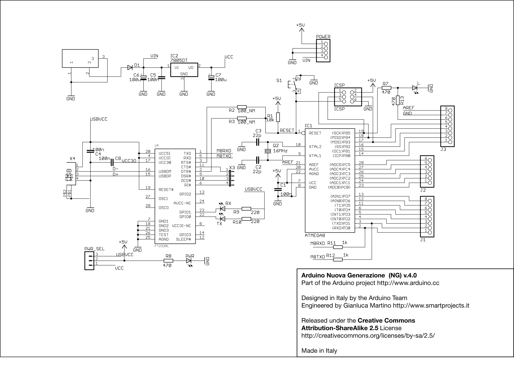
I see examples of the LED inserted into socket of 13 and gnd without a dropping resistor so I was scratching my head a bit as to the need for it.
OK, this relates to a very old Arduino, the "NG":
[Click image for full size]
Seems the "tutorials" are not quite up to date. Does this surprise you?
If I clamp the amps I can run the volts up to 30 and they survive.
No. You may be turning the voltage dial up to 30V but you are not getting 30V out of the PSU. Bench PSUs "clamp" the current by lowering the voltage when the current rises above the limit you set.


