Hello everyone. I am attempting to build an automated lego sorter. It will feature a conveyer driven by a stepper, using micro servos to sort, a TCS3200 and UNO.
I would like to initally start with sorting only 3 colors. Preferably Red, Green, Blue, and dump all other colors off the edge of the conveyer. I would like to change these as I need so I can sort other color bricks.
It is ok if it is not a 100% method, I need something to cut down hand sorting.
I found 2 codes that I would like to combine, but I need to also add something to tell the stepper to start and stop.
My basis initally was this project:
Sorting machine
Using this code:
#include <Servo.h>

Servo pickServo;

Servo dropServo;


#define S0 4

#define S1 5

#define S2 7

#define S3 6

#define sensorOut 8

int frequency = 0;

int color=0;


int detectColor() {

  // activating red photodiodes to read

  digitalWrite(S2, LOW);

  digitalWrite(S3, LOW);

  frequency = pulseIn(sensorOut, LOW);

  int R = frequency;

  Serial.print("Red = ");

  Serial.print(frequency);//printing RED color frequency

  Serial.print("   ");

  delay(50);


   // activating blue photodiodes to read

  digitalWrite(S2, LOW);

  digitalWrite(S3, HIGH);

  frequency = pulseIn(sensorOut, LOW);

  int B = frequency;

  Serial.print("Blue = ");

  Serial.print(frequency);

  Serial.println("   ");


  // activating green photodiodes to read

  digitalWrite(S2, HIGH);

  digitalWrite(S3, HIGH);

  // Reading the output frequency

  frequency = pulseIn(sensorOut, LOW);

  int G = frequency;

  Serial.print("Green = ");

  Serial.print(frequency);

  Serial.print("   ");

  delay(50);


  delay(50);


//Readings are different for different setup

//change the readings according your project and readings detected

  if(R<22 & R>20 & G<29 & G>27){

    color = 1; // Red

    Serial.print("Detected Color is = ");

    Serial.println("RED");

  }

  if(G<25 & G>22 & B<22 &B>19){

    color = 2; // Orange

      Serial.println("Orange  ");

  }

  if(R<21 & R>20 & G<28 & G>25){

    color = 3; // Green

      Serial.print("Detected Color is = ");

    Serial.println("GREEN");

  }

  if(R<38 & R>24 & G<44 & G>30){

    color = 4; // Yellow

       Serial.print("Detected Color is = ");

    Serial.println("YELLOW");

  }

  if (G<29 & G>27 & B<22 &B>19){

    color = 5; // Blue

     Serial.print("Detected Color is = ");

    Serial.println("BLUE");

  }

  return color;

}


void setup() {

  pinMode(S0, OUTPUT);

  pinMode(S1, OUTPUT);

  pinMode(S2, OUTPUT);

  pinMode(S3, OUTPUT);

  pinMode(sensorOut, INPUT);


  //frequency-scaling to 20% selected

  digitalWrite(S0, LOW);

  digitalWrite(S1, HIGH);


  pickServo.attach(9);

  dropServo.attach(10);


  Serial.begin(9600);

}


void loop() {

  //initial position of servo motor

  pickServo.write(115);

  delay(600);


  for(int i = 115; i > 65; i--) {

    pickServo.write(i);

    delay(2);

  }

  delay(500);

  //read color values by calling function. save the values for conclusion in variable

  color = detectColor();

  delay(1000);


  switch (color) {

    case 1:

    dropServo.write(50);


    break;


    case 2:

    dropServo.write(80);

    break;


    case 3:

    dropServo.write(110);

    break;


    case 4:

    dropServo.write(140);

    break;


    case 5:

    dropServo.write(170);

    break;


    case 0:

    break;

  }

  delay(500);


  for(int i = 65; i > 29; i--) {

    pickServo.write(i);

    delay(2);

  }

  delay(300);


  for(int i = 29; i < 115; i++) {

    pickServo.write(i);

    delay(2);

  }

  color=0;

}
However, with following his tutorial I could not get the correct RGB outputs, so I tried this one:
RGB Sensor
```
/*********
  Rui Santos
  Complete project details at https://randomnerdtutorials.com
*********/

// TCS230 or TCS3200 pins wiring to Arduino
#define S0 4
#define S1 5
#define S2 6
#define S3 7
#define sensorOut 8

// Stores frequency read by the photodiodes
int redFrequency = 0;
int greenFrequency = 0;
int blueFrequency = 0;

// Stores the red. green and blue colors
int redColor = 0;
int greenColor = 0;
int blueColor = 0;

void setup() {
  // Setting the outputs
  pinMode(S0, OUTPUT);
  pinMode(S1, OUTPUT);
  pinMode(S2, OUTPUT);
  pinMode(S3, OUTPUT);

  // Setting the sensorOut as an input
  pinMode(sensorOut, INPUT);

  // Setting frequency scaling to 20%
  digitalWrite(S0,HIGH);
  digitalWrite(S1,LOW);

  // Begins serial communication
  Serial.begin(9600);
}

void loop() {
  // Setting RED (R) filtered photodiodes to be read
  digitalWrite(S2,LOW);
  digitalWrite(S3,LOW);

  // Reading the output frequency
  redFrequency = pulseIn(sensorOut, LOW);
  // Remaping the value of the RED (R) frequency from 0 to 255
  // You must replace with your own values. Here's an example:
  // redColor = map(redFrequency, 70, 120, 255,0);
  redColor = map(redFrequency, XX, XX, 255,0);

  // Printing the RED (R) value
  Serial.print("R = ");
  Serial.print(redColor);
  delay(100);

  // Setting GREEN (G) filtered photodiodes to be read
  digitalWrite(S2,HIGH);
  digitalWrite(S3,HIGH);

  // Reading the output frequency
  greenFrequency = pulseIn(sensorOut, LOW);
  // Remaping the value of the GREEN (G) frequency from 0 to 255
  // You must replace with your own values. Here's an example:
  // greenColor = map(greenFrequency, 100, 199, 255, 0);
  greenColor = map(greenFrequency, XX, XX, 255, 0);

  // Printing the GREEN (G) value
  Serial.print(" G = ");
  Serial.print(greenColor);
  delay(100);

  // Setting BLUE (B) filtered photodiodes to be read
  digitalWrite(S2,LOW);
  digitalWrite(S3,HIGH);

  // Reading the output frequency
  blueFrequency = pulseIn(sensorOut, LOW);
  // Remaping the value of the BLUE (B) frequency from 0 to 255
  // You must replace with your own values. Here's an example:
  // blueColor = map(blueFrequency, 38, 84, 255, 0);
  blueColor = map(blueFrequency, XX, XX, 255, 0);

  // Printing the BLUE (B) value
  Serial.print(" B = ");
  Serial.print(blueColor);
  delay(100);

  // Checks the current detected color and prints
  // a message in the serial monitor
  if(redColor > greenColor && redColor > blueColor){
      Serial.println(" - RED detected!");
  }
  if(greenColor > redColor && greenColor > blueColor){
    Serial.println(" - GREEN detected!");
  }
  if(blueColor > redColor && blueColor > greenColor){
    Serial.println(" - BLUE detected!");
  }
}
I found that with my sensor:
Red 39, 226
Green 69, 286
Blue 27,97
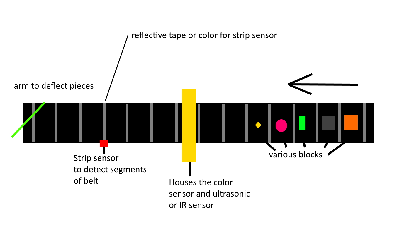
Again, I would like to pretty much merge these. I like the ability to change the 0-255 so I can tweak teh code as needed for the colors I am sorting. I am trying to make this thing as basic as I can. I have a very basic drawing of what I am trying to do:

This is the stepper tutorial I would like to use as well:
Thank you again for helping me. I am still a little new to this whole coding thing. I have only modified code for 3D printers.