So to be clear are the LEDs in the part of the display normally out of reach actually changing now? With the parts that changed before not changing?
Nothing but I did some tests using this sheet trying to figure out if it's from the wiring or from the code.
I used this sketch and changing in it gives me different results :
uint64_t row1[128];
//uint32_t row2[32];

uint64_t temp;

int LP = 8;            // Latch Pin
int ClkP = 12;         // Clock Pin
int R1P = 11;          // R1 Pin
int B1P = 10;          // B1 Pin
int G1P = 9;           // G1 Pin
int R2P = 7;           // R2 Pin
int B2P = 6;           // B2 Pin
int G2P = 5;           // G2 Pin
int AP = 2;            // A Pin
int BP = 3;            // B Pin
int CP = 4;            // C Pin
int OEP = 13;          // OE Pin
int row = 0;
uint64_t i;

void setup() {
//set pins to output so you can control the shift register
pinMode(LP, OUTPUT);
pinMode(ClkP, OUTPUT);
pinMode(R1P, OUTPUT);
pinMode(B1P, OUTPUT);
pinMode(G1P, OUTPUT);
pinMode(R2P, OUTPUT);
pinMode(B2P, OUTPUT);
pinMode(G2P, OUTPUT);
pinMode(AP,OUTPUT);
pinMode(BP,OUTPUT);
pinMode(CP,OUTPUT);
pinMode(OEP,OUTPUT);

digitalWrite(AP, LOW);
digitalWrite(BP, LOW);
digitalWrite(CP, LOW);
digitalWrite(LP, LOW);
digitalWrite(OEP, LOW);
row=0;
temp =  0x0000000000000000000000000001;

//------------------------Paste here:


row1[0]=0xC0C0C0FF030303FFC3C3C7FFC3C3C3FF;
row1[1]=0XC0C0C0FF030303FFC3C3CFC0C3C3C303;
row1[2]=0xC0C0C0C003030303C3C3DFC1C3C3C3C3;
row1[3]=0xC0C0C0C003030303C3C3DFC3C3C3C3C3;
row1[4]=0xC0C0C0C003030303DFDFC3C3FBFBC3C3;
row1[5]=0xC0C0C0C003030303C0DFC3C303FBC3C3;
row1[6]=0xFFC0C0C0FF030303FFDFC3C3FFFBC3C3;
row1[7]=0xFFC0C0C0FF030303FFDFC3C3FFFBC3C3;


//----------------------------up to here
}

void loop() {
for(row=0; row<4; row++){
   for (i = 0; i < 128; i++)  {
      digitalWrite(B1P, 0);
      digitalWrite(R1P, 0);
      digitalWrite(G1P, !!(row1[row] & (temp << (127-i))));
      digitalWrite(B2P, !!(row1[row+4] & (temp << (127-i))));
      digitalWrite(R2P, 0);
      digitalWrite(G2P, 0);
      digitalWrite(ClkP, HIGH);
      digitalWrite(ClkP, LOW);
      }
   digitalWrite(OEP, HIGH);
   digitalWrite(LP, HIGH);
   digitalWrite(AP, !!(row & B00000001));
   digitalWrite(BP, !!(row & B00000010));
   digitalWrite(CP, !!(row & B00000100));
   digitalWrite(OEP, LOW);
   digitalWrite(LP, LOW);
 shiftOut1(R1P, B1P, G1P, R2P, B2P, G2P, ClkP);
}
}

void shiftOut1(uint64_t R1P1, uint64_t B1P1, uint64_t G1P1, uint64_t R2P1, uint64_t B2P1, uint64_t G2P1, uint64_t ClkP1)
{
}
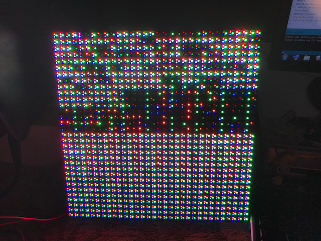
Result in (here) is the result of the inputs in the Excel sheet from one port and in realty is more clear and okay on just on the Exact right side only.
but then I tried to change in the code with the number 128 to make 64 and (127-i) to be (63-i)
with the same inputs and different drawing and it was giving me double picture of the right side but a little bit pulled down like in (Here).
then I used huidu led controller from only one port with the same wiring and it gave me (This).
So what I figured out the wiring is okay and it can be controlled from only on input port.
and we need to know how we can change in code to make it draw properly on both sides.